National Instruments NI 9421 Getting Started Manual
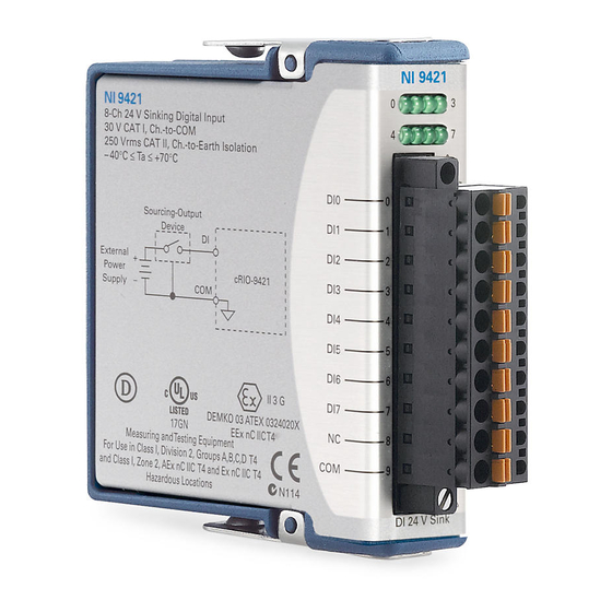
8-channel sinking digital input module
Hide thumbs
Also See for NI 9421:
- Operating instructions manual (28 pages) ,
- Getting started (10 pages)
Table of Contents
Advertisement
Quick Links
Advertisement
Table of Contents

Related Manuals for National Instruments NI 9421


Summary of Contents for National Instruments NI 9421
- Page 1 GETTING STARTED GUIDE NI 9421 8-Channel Sinking Digital Input Module...
-
Page 2: Safety Guidelines
This document explains how to connect to the NI 9421. In this document, the NI 9421 with screw terminal, NI 9421 with spring terminal, and NI 9421 with DSUB are referred to inclusively as the NI 9421. Before you begin, complete the software and... -
Page 3: Safety Guidelines For Hazardous Voltages
A hazardous voltage is a voltage greater than 42.4 Vpk voltage or 60 VDC to earth ground. You can connect hazardous voltages only to the NI 9421 with screw terminal and the NI 9421 with spring terminal. Do not connect hazardous voltages to the NI 9421 with DSUB. -
Page 4: Ni 9421 With Screw/Spring Terminal Safety Voltages
This category refers to local-level electrical distribution, such as that provided by a standard wall outlet, for example, 115 V for U.S. or 230 V for Europe. 4 | ni.com | NI 9421 Getting Started Guide... -
Page 5: Ni 9421 With Dsub Safety Voltages
MAINS voltage. MAINS is a hazardous live electrical supply system that powers equipment. This category is for measurements of voltages from specially protected secondary circuits. Such voltage measurements include signal levels, special NI 9421 Getting Started Guide | © National Instruments | 5... -
Page 6: Safety Guidelines For Hazardous Locations
CAT III, or CAT IV. Safety Guidelines for Hazardous Locations The NI 9421 is suitable for use in Class I, Division 2, Groups A, B, C, D, T4 hazardous locations; Class I, Zone 2, AEx nA IIC T4 and Ex nA IIC T4 hazardous locations; and nonhazardous locations only. - Page 7 II 3G and is suitable for use in Zone 2 hazardous locations, in ambient temperatures of -40 °C ≤ Ta ≤ 70 °C. If you are using the NI 9421 in Gas Group IIC hazardous locations, you must use the device in...
-
Page 8: Electromagnetic Compatibility Guidelines
This product was tested and complies with the regulatory requirements and limits for electromagnetic compatibility (EMC) stated in the product specifications. These requirements and limits provide reasonable protection against harmful interference 8 | ni.com | NI 9421 Getting Started Guide... -
Page 9: Special Conditions For Marine Applications
(shipboard) applications. To verify Lloyd’s Register certification for a product, visit ni.com/certification and search for the LR certificate, or look for the Lloyd’s Register mark on the product. NI 9421 Getting Started Guide | © National Instruments | 9... -
Page 10: Preparing The Environment
EMC performance is attained. Preparing the Environment Ensure that the environment in which you are using the NI 9421 meets the following specifications............Operating temperature -40 °C to 70 °C (IEC 60068-2-1, IEC 60068-2-2) ............ -
Page 11: Connecting The Ni 9421
Refer to the device datasheet on ni.com/manuals Note for complete specifications. Connecting the NI 9421 The NI 9421 provides connections for eight digital input channels. NI 9421 Getting Started Guide | © National Instruments | 11... - Page 12 You must use 2-wire ferrules to create a secure Note connection when connecting more than one wire to a single terminal on the NI 9421 with screw terminal or NI 9421 with spring terminal. 12 | ni.com | NI 9421 Getting Started Guide...
-
Page 13: Connecting Sourcing-Output Devices
NI 9421 Signals Each channel of the NI 9421 has a DI terminal or pin to which you can connect voltage or current signals. The NI 9421 also has COM, a common terminal or pin that is internally connected to the isolated ground reference of the module. -
Page 14: Led Indications
Figure 2. Connecting a Device to the NI 9421 (3-Wire Device Shown) Sourcing-Output Device External Power Supply – NI 9421 The NI 9421 channel registers as ON when the sourcing-output device applies a voltage or drives a current that is in the input ON range to DI. -
Page 15: High-Vibration Application Connections
• Use ferrules to terminate wires to the detachable connector. • Use the NI 9927 backshell kit with the NI 9421 with screw terminal or the NI 9981 backshell kit with the NI 9421 with spring terminal. NI 9421 Getting Started Guide | © National Instruments | 15... -
Page 16: Where To Go Next
NI 9421 Datasheet NI 9421 Datasheet NI-RIO Help NI-DAQmx Help LabVIEW FPGA Help LabVIEW Help RELATED INFORMATION C Series Documentation Services & Resources ni.com/services ni.com/info cseriesdoc Located at ni.com/manuals Installs with the software 16 | ni.com | NI 9421 Getting Started Guide... -
Page 17: Worldwide Support And Services
You can obtain the DoC for your product by visiting ni.com/certification. If your product supports calibration, you can obtain the calibration certificate for your product at ni.com/calibration. NI 9421 Getting Started Guide | © National Instruments | 17... - Page 18 Refer to the NI Trademarks and Logo Guidelines at for information on ni.com/trademarks National Instruments trademarks. Other product and company names mentioned herein are trademarks or trade names of their respective companies. For patents covering National Instruments products/technology, refer to the appropriate location: Help»Patents in your software, file on your media, or the National Instruments Patent Notice at patents.txt...
Need help?
Do you have a question about the NI 9421 and is the answer not in the manual?
Questions and answers