Table of Contents
Advertisement
Advertisement
Table of Contents

Related Manuals for Edwards iXL120


Summary of Contents for Edwards iXL120
- Page 1 A591-40-880 Issue A Original Instruction Manual iXL120 Dry Pump System...
-
Page 2: Declaration Of Conformity
- in homogeneous materials (subject to the exemptions allowed by the Directive). This information relates only to products sold on or after the date of this certificate. Edwards has taken all reasonable steps to confirm this statement, which is based mainly on information from our suppliers. Whilst the RoHS Directive does not legally apply to this vacuum equipment, we recognize that component compliance is relevant to many of our customers. - Page 3 Removing the iXL120 system from the packaging ..............14 Locate the iXL120 .......................15 Connect the iXL120 system to your vacuum/exhaust system and interstage connection (if fitted) ..15 Leak test the iXL120 system ..................16 Connect the nitrogen supply ..................16 3.6.1...
- Page 4 Other ........................52 A2.4.1 Pump controller communications ..................52 For return of equipment, complete the HS Forms at the end of this manual. Page ii © Edwards Limited 2012. All rights reserved. Edwards and the Edwards logo are trademarks of Edwards Limited.
- Page 5 Display inverter fault history menu .................. 44 Fit accessory menu .....................45 IP configuration menu ....................45 Display menu ......................46 Display menu select line ....................46 © Edwards Limited 2012. All rights reserved. Page iii Edwards and the Edwards logo are trademarks of Edwards Limited.
- Page 6 Harting Electric GmbH ® EtherCon is a registered trademark of Neutrik® AG ® Fomblin is a registered trademark of Solvay Solexis SpA Page iv © Edwards Limited 2012. All rights reserved. Edwards and the Edwards logo are trademarks of Edwards Limited.
-
Page 7: Scope And Definitions
Introduction Scope and definitions This manual provides installation, operation and maintenance instructions for the Edwards iXL120 Pump. You must use your pump as specified in this manual otherwise the protection provided by the equipment may be impaired. Read this manual before you install and operate your pump. Important safety information is highlighted as WARNING and CAUTION instructions;... -
Page 8: Applications
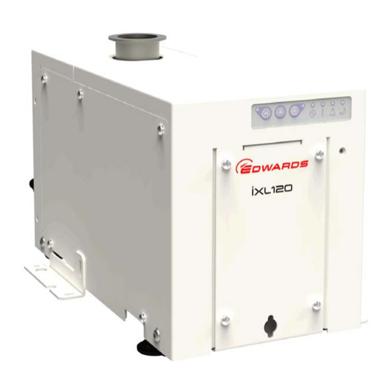
Applications The iXL120 is a low energy, compact dry pump system that can be mounted on tool or remotely. It is designed to give extremely low cost of ownership. The iXL120 is intended only for use on clean duty applications as defined in... -
Page 9: The Ixl120 System
The iXL120 system The iXL120 is a compact dry pump system that can be mounted on tool or remotely. The pumping system can be controlled from the front control panel, a PDT accessory or by the tool via a MicroTIM. -
Page 10: Priority Of Control
Pump Display Terminal (PDT) accessory or from the tool via the MicroTIM. Only one of these can have control of the iXL120 system at any one time. That is, once one of these has control of the iXL120 system, control requests from the others are denied until control is released by the first. -
Page 11: Technical Data
Stainless steel, aluminium, PTFE and fluoroelastomer Degree of protection Enclosure protection IP31D (EN60529: Degrees of protection provided by provided by enclosure when installed enclosures) © Edwards Limited 2012. All rights reserved. Page 5 Edwards and the Edwards logo are trademarks of Edwards Limited. -
Page 12: Loading
Table 3 - Levelling foot loads (refer to Figure 4) Levelling foot identifier Levelling foot load (kg) Figure 4 - Centre of gravity and levelling foot loads Page 6 © Edwards Limited 2012. All rights reserved. Edwards and the Edwards logo are trademarks of Edwards Limited. -
Page 13: Electrical Data
Contact Edwards for more information about configuration requirements for Earth leakage reduction. Table 5 - Electrical ratings: ultimate vacuum and extracted (700 torr) exhaust load condition Electrical sub-system: ultimate vacuum (0.01 mbar) load rating... -
Page 14: Electrical Ratings: Full Load Conditions
7, does NOT include the power consumption of the pump’s internal auxiliary power-supply. This auxiliary power-supply is used to power the pump’s motor-controller, pump-controller and customer accessories. Page 8 © Edwards Limited 2012. All rights reserved. Edwards and the Edwards logo are trademarks of Edwards Limited. -
Page 15: Electrical Connections And Cables
Pin 4 – Gate valve drive transistor (open collector) Gate valve position sense: Pin 7 – ‘Closed’; Pin 8 – ‘Open’ © Edwards Limited 2012. All rights reserved. Page 9 Edwards and the Edwards logo are trademarks of Edwards Limited. -
Page 16: Input Supply Wire Assembly
(380 – 460 V a.c., rms / 50 – 60 Hz) Conductor wire type Stranded wires ° Conductor insulation min temperature rating Page 10 © Edwards Limited 2012. All rights reserved. Edwards and the Edwards logo are trademarks of Edwards Limited. -
Page 17: Cooling Water Data
The table specifies minimum water flow rate that is required at 30 °C cooling water. The water flow rate can be reduced if colder water is supplied. Contact Edwards for additional information. Maximum flow of 5 l min to prevent condensation at 10 °C cooling water. - Page 18 A591-40-880 Issue A This page has been intentionally left blank. Page 12 © Edwards Limited 2012. All rights reserved. Edwards and the Edwards logo are trademarks of Edwards Limited.
-
Page 19: Installation
Edwards publication ‘Vacuum Pump and Vacuum System Safety’ (publication number P400-40-100). Only Edwards trained engineers may install the dry pumping system. Users can be trained by Edwards to conduct the tasks described in this manual, contact your local service centre or Edwards for more information. -
Page 20: Removing The Ixl120 System From The Packaging
3.4. 9. The iXL120 system is ready to be located; please refer Section 3.3 of the manual. Page 14 © Edwards Limited 2012. All rights reserved. Edwards and the Edwards logo are trademarks of Edwards Limited. -
Page 21: Locate The Ixl120
3.2) to move the iXL120 system close to its final operating position. 2. Adjust the levelling feet to make sure that the iXL120 system is level and is not supported by the castors. 3. The lifting brackets should be removed and retained. -
Page 22: Leak Test The Ixl120 System
Incorporate a pressure gauge in the inlet pipeline, as an aid to determining that the iXL120 system operates correctly. You must be able to isolate the iXL120 system inlet from the atmosphere and from your vacuum system if you have pumped or produced corrosive chemicals. -
Page 23: Gas Purges
Gas purges WARNING The iXL120 pumps are not suitable for use with hazardous production materials. Any hazardous production materials must be diluted to a safe level before entering the pump. Gas purge is provided for the sole purpose of enabling the pumping of inert light gases such as helium. - Page 24 Use the following procedure and connector components supplied with the pump to connect the electrical supply to the iXL120 system. When you make the electrical supply cable, ensure that the Earth (ground) conductor is slightly longer than the phase conductors. This will ensure that if the cable is accidentally dragged and the strain relief bush on the electrical supply connector mating-half fails, the Earth (ground) conductor will be the last conductor to be pulled from the connector.
-
Page 25: Connect The Electrical Supply
1. 3-Phase mains cable. 5. Screw Module (female) 2. Cable gland 6. Housing 3. Hood (M25) 7. Screws x 4 4. Gasket © Edwards Limited 2012. All rights reserved. Page 19 Edwards and the Edwards logo are trademarks of Edwards Limited. -
Page 26: Electrical Connector Locking Mechanism
EMS connector (Figure 2, item 15) on the rear of the iXL120 system. If you do not, you will not be able to operate the iXL120 system. If required, you can connect your own control equipment to the iXL120 system to shut it down in an emergency... -
Page 27: Connect To Your Control Equipment
5 V selects inactive. 3. To ensure correct pump operation, at least 10 seconds must be allowed between successive operations of the input signals. © Edwards Limited 2012. All rights reserved. Page 21 Edwards and the Edwards logo are trademarks of Edwards Limited. -
Page 28: Connect The Cooling-Water Hoses
(Figure 3, item 3). The green LED will illuminate. Then press the Start button (Figure 3, item 1). 6. If the iXL120 system starts and continues to operate, continue at Step 7. If a warning or alarm condition is indicated:... -
Page 29: Operation
Press and hold the Start button (Figure 3, item 1) until pumps starts and the Running LED (Figure 3, item 1) is illuminated. © Edwards Limited 2012. All rights reserved. Page 23 Edwards and the Edwards logo are trademarks of Edwards Limited. -
Page 30: Status Indicators
Use your control equipment to reset the pump start/stop signal to the interface connector. The Running LED (Figure 3, item 1) will then go off, and the pump running status output signal will open. Page 24 © Edwards Limited 2012. All rights reserved. Edwards and the Edwards logo are trademarks of Edwards Limited. -
Page 31: Automatic Shut-Down
If the iXL120 system has an unplanned shut down or alarm, ensure that the cause of the shut down or alarm is identified and rectified before restarting. If you have a PDT connected to the pump then you should note and record... -
Page 32: Emergency Stop (Ems)
(see Section 7.3). To shut down the iXL120 system in an emergency, you can operate the emergency stop controls in your own control system if you have connected your emergency stop circuit to the iXL120 system as described in Section 3.7.1. -
Page 33: Auto Tune Configuration
2. Press ENTER. 3. Use up and down arrows to set target pressure. 4. Press ENTER to confirm. All other parameters are set to factory defaults. Please contact Edwards for advice on setting these values for your application. 4.8.4 Starting the Auto Tune process From the Auto Tune menu on the PDT: 1. -
Page 34: Important Notes About Auto Tune
The Auto Tune settings are pump-specific, they are not stored in the MicroTIM. If the pump is replaced, the Auto Tune process must be performed on the replacement pump. Page 28 © Edwards Limited 2012. All rights reserved. Edwards and the Edwards logo are trademarks of Edwards Limited. -
Page 35: Maintenance
260 °C. Refer to Edwards Material Safety Data Sheets for detailed information. Ensure that the maintenance technician is familiar with the safety procedures which relate to the process ... -
Page 36: Relocate The System For Maintenance
Fluorinated materials in the iXL120 system may include oils, greases and seals. The iXL120 system may have overheated if it was misused, if it malfunctioned or if it was in a fire. Edwards Material Safety Data Sheets for fluorinated materials used in the pump are available on request: contact your supplier or Edwards. -
Page 37: Draining The Cooling Water
4. Disconnect the inlet and outlet from the vacuum and exhaust systems and fit blanking caps. 5. Adjust the levelling feet so that the iXL120 system rests on the castors. 6. Move the iXL120 system to a location where it can be safely stored until an Edwards service engineer can be in attendance. -
Page 38: General Maintenance
The system is given a charge of oil before it leaves the factory. There is no requirement to adjust the oil level. You can conduct the following maintenance on the system when necessary or if you have a problem, contact Edwards... -
Page 39: Transportation, Storage And Disposal
Perchlorate Material - special handling may apply, refer to www.dtsc.ca.gov/hazardouswaste/perchlorate/ Edwards products are supported by a world-wide network of Edwards Service Centres. Each Service Centre offers a wide range of options including disposal. Refer to Section 7.2... - Page 40 A591-40-880 Issue A This page has been intentionally left blank. Page 34 © Edwards Limited 2012. All rights reserved. Edwards and the Edwards logo are trademarks of Edwards Limited.
-
Page 41: Service, Spares And Accessories
For more information about service options, contact your nearest Service Centre or other Edwards company. Accessories The accessories available for use with the iXL120 dry pump system are described in the following sections. Figure 7 shows how the accessories are fitted to the iXL120 dry pump system. -
Page 42: Ems Button
7.3.3 Accessory modules Two accessory modules are available for the iXL120 dry pump system. The Active Accessory Module (AAM) provides connectivity for up to three directly connected accessories including a gate valve, abatement and water flow sensor, plus up to two supported active accessories, two thermocouples and the pump status output. The Passive Accessory Module (PAM) allows up to 3 accessories to be connected to the accessory module interface. -
Page 43: Pdt Extension Cable
Main power connector A replacement 3-phase supply and PE connector. Table 26 - Main power connector Item Item number Main power connector D37491735 © Edwards Limited 2012. All rights reserved. Page 37 Edwards and the Edwards logo are trademarks of Edwards Limited. -
Page 44: Ems Terminator Plug
Emergency stop D37370310 MCM EMS Module Emergency stop D37370320 LAM Alliance EMS Module Emergency stop D37370350 C3 EMS Module Emergency stop D37370360 Page 38 © Edwards Limited 2012. All rights reserved. Edwards and the Edwards logo are trademarks of Edwards Limited. -
Page 45: Accessories
5. PDT adaptor cable 2. EMS button 6. PDT extension cable 3. Accessory module Note: Some cables omitted for clarity 4. PDT © Edwards Limited 2012. All rights reserved. Page 39 Edwards and the Edwards logo are trademarks of Edwards Limited. - Page 46 A591-40-880 Issue A This page has been intentionally left blank. Page 40 © Edwards Limited 2012. All rights reserved. Edwards and the Edwards logo are trademarks of Edwards Limited.
-
Page 47: A1.1 Pdt
Red illuminates to indicate that a pump alarm is present. It flashes when a new alarm occurs until it is acknowledged by pressing ENTER when it goes continuous until the alarm clears. © Edwards Limited 2012. All rights reserved. Page 41 Edwards and the Edwards logo are trademarks of Edwards Limited. -
Page 48: A1.1.2 Pump Start / Stop And Control
Once all warning/alarm conditions have gone away, then the corresponding LED is extinguished. To avoid a build up of out of date Warnings they are automatically acknowledged after 36 hours. Page 42 © Edwards Limited 2012. All rights reserved. Edwards and the Edwards logo are trademarks of Edwards Limited. -
Page 49: A1.1.4 Menus
Run Hours RUN HOURS 1000 Number of Pump Starts PUMP STARTS Time to Stop (seconds) TIME TO STOP Active Alarms and Warnings © Edwards Limited 2012. All rights reserved. Page 43 Edwards and the Edwards logo are trademarks of Edwards Limited. -
Page 50: A5 Setup Menu
Under the Setup menu. Scroll through the software version loaded in the processors by pressing up/down keys. Press CANCEL to exit back to the SETUP menu. Page 44 © Edwards Limited 2012. All rights reserved. Edwards and the Edwards logo are trademarks of Edwards Limited. -
Page 51: A8 Fit Accessory Menu
Edit IP menu. Pressing CANCEL at the start of the line will cancel and exit back to the IP Configuration menu. Display only items press CANCEL to exit back to the IP Configuration menu. © Edwards Limited 2012. All rights reserved. Page 45 Edwards and the Edwards logo are trademarks of Edwards Limited. -
Page 52: A10 Display Menu
In each option scroll through the units available by pressing up/down keys. Press ENTER to select the displayed units or CANCEL to exit back to the UNITS menu. Page 46 © Edwards Limited 2012. All rights reserved. Edwards and the Edwards logo are trademarks of Edwards Limited. -
Page 53: Troubleshooting
Valve Not Shut supply to the Gate valve. Note: This warning will only clear when the valve has successfully been opened and closed. © Edwards Limited 2012. All rights reserved. Page 47 Edwards and the Edwards logo are trademarks of Edwards Limited. -
Page 54: A2.2 Alarms
Table A14 lists the alarm messages that might be displayed on the PDT with possible causes and actions you should take. Page 48 © Edwards Limited 2012. All rights reserved. Edwards and the Edwards logo are trademarks of Edwards Limited. -
Page 55: A2.3 Inverter Warnings And Alarms
To decode inverter warning and alarm codes, refer to Table A15 to convert the hexadecimal digits into alert combinations and then refer to Table A16 and A17). © Edwards Limited 2012. All rights reserved. Page 49 Edwards and the Edwards logo are trademarks of Edwards Limited. - Page 56 Check EMS button and EMS plug in the back of pump. DESAT_FAULT Internal fault contact Edwards UNDERT Inverter is too cold. See warning register to determine source of problem. Page 50 © Edwards Limited 2012. All rights reserved. Edwards and the Edwards logo are trademarks of Edwards Limited.
- Page 57 Internal power supply fault - contact Edwards LOWTC Low controller temperature - contact Edwards LOWTS Low heatsink temperature - contact Edwards CAN LOSS Reserved © Edwards Limited 2012. All rights reserved. Page 51 Edwards and the Edwards logo are trademarks of Edwards Limited.
-
Page 58: A2.4 Other
Gate valve will close. The pump will stop immediately without any gas purges. Any requests to start the pump will be rejected until the fault has been rectified. Page 52 © Edwards Limited 2012. All rights reserved. Edwards and the Edwards logo are trademarks of Edwards Limited.
Need help?
Do you have a question about the iXL120 and is the answer not in the manual?
Questions and answers