VeriFone M400 Installation Manual
Payment device
Hide thumbs
Also See for M400:
- Quick start manual (2 pages) ,
- Installation manual (41 pages) ,
- User manual & setup manual (11 pages)
Table of Contents
Advertisement
Advertisement
Table of Contents

Related Manuals for VeriFone M400


Summary of Contents for VeriFone M400
- Page 1 M400 Installation Guide Verifone Part Number DOC445-003-EN-A, Revision A.7...
- Page 2 Verifone, Inc. The in formation cont ained in this d ocument is subj ect to chan ge wi thout notice. Alth ough Verifone ha s attempted to en sure the accuracy of the contents of this document, this document may include errors or omissions. The examples and sample programs are for illustration only and may not be suited for your purpose.
- Page 3 M400 Connection Options ........
- Page 4 Transactions Fail To Process ........42 M400 I...
-
Page 5: P Reface
M400 Certifications and Regulations VPN - DOC445-002-EN M400 Series Quick Installation Guide VPN - DOC445-005-EN M400 Series Ice Cube Certifications and Regulations VPN - DOC445-006-EN M400 Series Ice Cube Quick Installation Guide VPN - DOC445-007-EN M400 Series Stand Quick Installation Guide... -
Page 6: Guide Conventions
The pencil icon is used to RS232-type devices do not work NOTE highlight important information. on the M400 communication port. The caution symbol indicates The unit is not waterproof or hardware or software failure, or dustproof, and is intended for CAUTION loss of data. -
Page 7: Acronym Definitions
Multiple Secure Access Module Operating System Personal Identification Number Point-of-Sale RFID Radio Frequency Identification Secure Access Module Smart Card (Integrated Chip Card) Secure Digital Ship Release SRAM Static Random Access Memory User Interface Universal Serial Bus Wi-Fi Wireless Fidelity M400 I NSTALLATION UIDE... - Page 8 REFACE Guide Conventions M400 I NSTALLATION UIDE...
- Page 9 PCI 4.x security, and an integrated contactless module. M400 WiFi/BT supports 802.11 a/b/g/n Wireless Fidelity (Wi-Fi) and Bluetooth (BT), while the M400 BT variant supports Bluetooth (BT) including BLE with iBeacon and Eddystone profiles . Figure 1...
-
Page 10: Performance And Durability
Simple, plug-and-play installation for locations that need short- Communication • range wireless capability. Eddystone and iBeacon profiles are also supported. Technology Wi-Fi: Ideal for retailers that need multiple wireless devices and have an • existing IP infrastructure (M400 WiFi-BT only). M400 I NSTALLATION UIDE... -
Page 11: Setup Terminal Location
Ease of Use • Select a flat support surface, such as a countertop or table, or mount it on a • mounting stand supplied by Verifone. Select a location near a power outlet, POS, ECR, or computer connected to •... -
Page 12: Electrical Considerations
Install the PED on an adjustable stand that allows consumers to swivel the • terminal sideways and/or tilt it forwards/backwards to a position that makes visual observation of the PIN-entry process difficult. Position in-store security cameras so that the PIN-entry keypad is not visible. • M400 I NSTALLATION UIDE... - Page 13 If the unit will be swiveled during normal operation, Verifone requires the use of an approved swivel stand. Special care is required when mounting the M400 terminal in sites that utilize NOTE anti-theft devices positioned at doorways or surface mounted deactivator pads.
-
Page 14: Inside The Shipping Carton
Do not use a tampered or damaged unit. The terminal comes equipped with WARNING tamper-evident labels. If a label or component appears damaged, please notify the shipping company and your Verifone service provider immediately. M400 I NSTALLATION UIDE... -
Page 15: Terminal Features
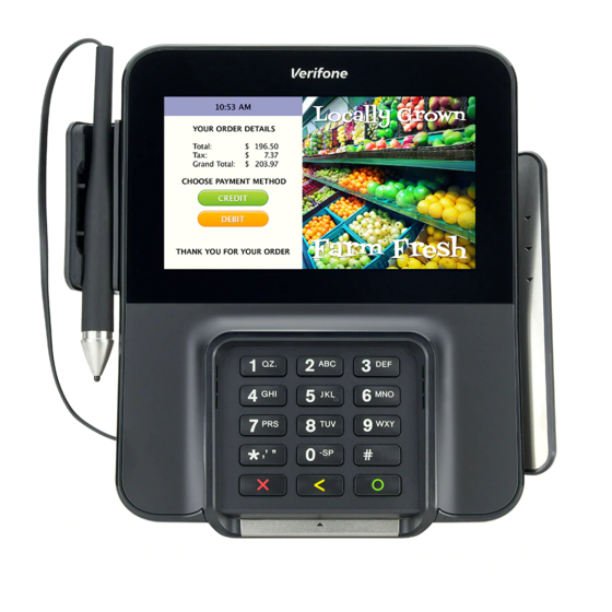
TELCO-STYLE KEYPAD MAGNETIC CARD READER AUDIO JACK SMART CARD READER Figure 2 M400 Features The front panel offers the following features: Front Panel A touchscreen display. • A set of keys that include: • A 12-key, telco-style keypad (keypads may vary in style). -
Page 16: Connection Ports
Cable provides multiple connection options. See Figure 7 for reference. Figure 4 USB Type C Cable Connected on the Rear of the Unit Close cable compartment as shown below (optional). Figure 5 Closing Cable Compartment with Cable Cover M400 I NSTALLATION UIDE... -
Page 17: M400 Connection Options
ETUP M400 Connection Options The M400 terminal can be connected to other systems using several methods. M400 They all connect to the M400 using the USB Type C cable connected on the rear Connection of the unit. Options Powered USB cable (PN CBL445-003-01-A) provides USB signal connectivity Powered USB Cable and power. -
Page 18: Ice Cubes
ETUP M400 Connection Options A set of modules that allow easy, economical, and efficient custom configuration ICE Cubes of communications options. Each configuration is comprised of a bas e module, an end cap, and a combination of other modules that support different communications interfaces, see Figure 7 as an example. -
Page 19: Ice Cube Modules
The available module functions are provided below: Base Module (PN 445-101-01-A) Provides the interface to the M400 terminal through the USB type C connector in the rear of the unit and the optional ICE cube modules. It has: Interface to the M400 terminal •... - Page 20 ETUP M400 Connection Options USB Interface Module (PN 445-103-01-A) This module has: ICE cube bus in • ICE cube bus out • RJ-50 with USB signals • Figure 10 USB Interface Module Ethernet Interface Module (PN 445-104-01-A) This module support 10/100 Mbits/sec and has: ICE cube bus in •...
- Page 21 ETUP M400 Connection Options Ethernet Switch Interface Module (PN 445-105-01-A) This module has a 2 port Ethernet switch and supports 10/100 Mbits/sec and has: Ice cube bus in • Ice cube bus out • Two RJ-50 with USB signals •...
-
Page 22: Supported Ice Cube Configurations
Base Module + Ethernet Switch Module Ethernet Switch with Tailgate CBL445-011-00-A Base Module + Ethernet Switch Module+ Tailgate M400 supports micro SD for additional memory. Micro SD Card To install or replace Micro SD card: Installing or Replacing Micro SD Turn off the terminal. -
Page 23: Msam Card
MSAM Card cards or replace an old one. Observe standard precautions in handling electrostatically sensitive devices. CAUTION Electrostatic discharge can damage the equipment. Verifone recommends using a grounded anti-static wrist strap. To install or replace MSAM cards: Installing or Replacing MSAM Power off the terminal. -
Page 24: Terminal Power Source
Disconnecting power during a transaction can also cause unstored data files to be lost. NOTE Verifone recommends installing a power surge protector to protect against possible damage caused by lightning strikes and electrical surges. To connect M400 terminal to a power source:... -
Page 25: Calibrate Touch Panel
Remove the card only when the display indicates the transaction is complete. Figure 17 Smart Card Reader CAUTION Leave the smart card in the card reader until the transaction is completed. Premature card removal can invalidate a transaction. M400 I NSTALLATION UIDE... -
Page 26: Magnetic Card Reader
An activated LED visual on the display accompanied by a short beeping sound indicates a successful transaction. Figure 19 Contactless Smart Card Transaction CAUTION Do not let metallic surfaces come in contact with the contactless module to ensure that it works properly. M400 I NSTALLATION UIDE... -
Page 27: M400 Wifi/Bt Support
ETUP M400 WiFi/BT Support M400 WiFi/BT version includes an integrated WLAN RF transceiver for Wireless M400 WiFi/BT LAN systems with advanced power management, and an integrated radio Support transceiver for Bluetooth wireless systems. Supports Eddystone and iBeacon profiles only. Bluetooth Support M400 supports wireless transactions. -
Page 28: Stand
Stand during customer pin entry. The stand can be positioned on a countertop and can be adjusted during transactions for convenience. Figure 23 M400 Series Stand To dock the terminal on the stand: Docking the Terminal on the Stand Place the terminal on the base. Ensure that the stand screws align with the keyholes found at the back of the terminal. - Page 29 Undocking the Terminal from the Slide off terminal upward to unhook the terminal from the stand. Stand Figure 26 Undocking Terminal from the Stand Lift terminal off the stand. Figure 27 Lifting Terminal off the Stand M400 I NSTALLATION UIDE...
-
Page 30: External And Optional Devices
PINpad through a serial or USB Host connection. See Figure 7 reference. Remove the power cord from the base module before connecting any peripheral CAUTION device. Reconnect the power cord only after you have finished connecting the peripheral device(s). M400 I NSTALLATION UIDE... -
Page 31: Chapter
• 5” IPS LCD Display • Triple track (tracks 1, 2, 3), high coercivity, bi-directional Magnetic Card • Reader ISO 7816, 1.8 V, 3 V, 5 V Primary Smart • Card Synchronous and asynchronous cards • M400 I NSTALLATION UIDE... -
Page 32: Sam Card Reader
USB Type C port for ICE Cube Base module connection. Peripheral Ports • one Micro-USB port for a graphometric stylus connection. • Complies to PCI 4.x requirements, as well as many regional security Security requirements. M400 I NSTALLATION UIDE... -
Page 33: C Hapter
If your device is not working properly, take it to the nearest authorized service facility for servicing or replacement. For your safety, have this device serviced only by a Verifone-authorized service provider. Never use thinner, trichloroethylene, or ketone-based solvents – they can CAUTION deteriorate plastic or rubber parts. -
Page 34: Potentially Explosive Environments
If unit shows no presence of foreign objects, test the SCR function and record results. Proceed to Step Send your terminal to a Verifone authorized repair center if foreign objects CAUTION are found in the SCR at any time during SCR inspection, test diagnostics, or cleaning process. - Page 35 Smart Card use. If SCR tests out as “failing”, then send the unit for repair. Provide details to repair center when SCR failed testing, either before cleaning OR after cleaning OR both before and after cleaning. M400 I NSTALLATION UIDE...
- Page 36 AINTENANCE AND LEANING Additional Safety Information M400 I NSTALLATION UIDE...
-
Page 37: Service And Support Service Returns
Step 1, to the MRA department at 1-727-953- 4172 (U.S.). Address the fax clearly to the attention of the “Verifone MRA Dept.” Include • a telephone number where you can be reached and your fax number. Complete the Inquiry Contact Form at http://www.verifone.com/aboutus/ •... -
Page 38: Accessories And Documentation
Reference the model and part number in the Note box • NOTE One MRA number must be issued for each terminal you return to Verifone, even if you are returning several of the same model. Describe the problem(s). Provide the shipping address where the repaired or replacement unit must be returned. - Page 39 M400 Certifications and Regulations VPN - DOC445-002-EN M400 Series Quick Installation Guide VPN - DOC445-005-EN M400 Series Ice Cube Certifications and Regulations VPN - DOC445-006-EN M400 Series Ice Cube Quick Installation Guide VPN - DOC445-007-EN M400 Series Stand Quick Installation Guide...
- Page 40 ERVICE AND UPPORT Accessories and Documentation M400 I NSTALLATION UIDE...
- Page 41 Please read these troubleshooting examples if you are having problems operating your unit. Contact your local Verifone representative for assistance if the problem persists even after performing the outlined guidelines or if the problem is not described.
-
Page 42: Blank Display
If the display does not show correct or readable information, check all cable • connections. If the problem persists, contact your local Verifone representative for assistance. If the keypad does not respond properly:... - Page 43 ROUBLESHOOTING UIDELINES Transactions Fail To Process M400 I NSTALLATION UIDE...
-
Page 44: Installation Guide
Verifone, Inc. 1-800-Verifone www.verifone.com M400 Installation Guide Verifone Part Number DOC445-003-EN-A, Revision A.7...
Need help?
Do you have a question about the M400 and is the answer not in the manual?
Questions and answers