Table of Contents
Advertisement
Advertisement
Table of Contents

Related Manuals for Senci SC2000i


Summary of Contents for Senci SC2000i
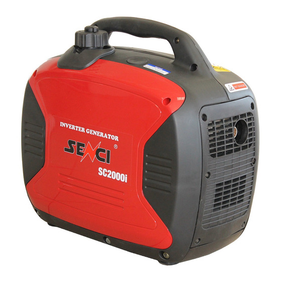
- Page 1 Inverter Generator specification...
- Page 2 WARNING The engine exhaust from this product Contains chemicals to cause cancer, birth Defects or other reproductive harm. Read this manual carefully before operating this machine. This manual should stay with this machine if it is sold. The pictures in the manual are just for reference.
- Page 3 INTRODUCTION Congratulations on your purchase of your new YAMAHA powered gasoline generator set This manual will provide you with a good basic understanding of the operation and maintenance of this machine.
- Page 4 IMPOTANT MANUAL INFORMATION Particularly important information is distin- Guished in this manual by the following notations. This is the safety alert symbol. it is Used to alert you to potential personal injury hazards. Obey all safety messages that follow this symbol to avoid Possible injury or death.
- Page 5 CONTENTS SAFETY INFORMATION…………..1 Application range……………………..20 EXHAUST FUMES ARE PERIODIC MAINTENANCE…………… ...21 POISONOUS………………………….1 Maintenance chart……………………..21 FUEL IS HIGHLY FLAMMABLE AND Spark plug inspection………………….23 POISONOUS………………………….1 carburetor adjustment…………………24 RNGINE AND MUFFLER MAY BE Engine oil replacement………...………24 HOT ENGINE………………………….1 Air filter………………………………….,26 ELCTRIC SHOCK PREVENTION…..2 Muffler screen and spark arrester……….27 CONNECTION NOTES………………3 Fuel tank filter………………………...…...29...
-
Page 6: Safety Information
AE00071 SAFETY INFORMATION AE0072 EXHAUST FUMES ARE POISONOUS ·Never operate the engine in a closed area or it may cause unconsciousness and death within a short time. Operate the engine in a well ventilated area. AE00075 FUEL IS HIGHLY FLAMMABLE AND POISONOUS ·Always turn off the engine when refueling. -
Page 7: Electric Shock Prevention
·Keep the machine at least 1m(3 ft)from buildings or other equipment, or the engine may overheat. @ 1 m(3 ft) ·Do not operate the engine with a dust cover, or other objects covering it. ·When covering the generator, be sure to do so only after the engine and muffler have completely cooled down. -
Page 8: Connection Notes
·Connect the ground lead of the machine to the ground (Earth) terminal 1 and connect the end to the ground electrode buried in the ground. AE00088 CONNECTION NOTES ·Avoid connecting the generator to commercial power outlet. ·Avoid connecting the generator in parallel with any other generator ①... -
Page 9: Location Of Important Labels
LOCATION OF IMPORTANT LABELS Please read the following labels carefully before oper- ating this machine. Maintain or replace safety and instruction labels, as necessary. ①... - Page 10 ② ③ ④...
-
Page 11: Description
DESCRIPTION ① carrying handle ② fuel tank cap air vent knob ③ fuel tank cap ④ recoil starter ⑤ fuel gauge ⑥ muffler ⑦ oil filler cap Control panel ① Oil warning light ② AC pilot light ③ Overload indicator light ④... -
Page 12: Control Function
CONTROL FUNCTION Engine switch The engine switch controls the ignition system. ① “ON” Lgnition circuit is switched on. The engine can be started. ② “stop” Lgnition circuit is switched off. The engine will not run, OIL Warning light (Red) When the oil level falls below the lower, the oil warning light comes on and then the engine stops auto- matically. -
Page 13: Economy Control Switch
Reduce the load of the connected electric device below the specified rated output of the generator if the DC protractor turns off again, stop using the device immediately and consult a Yamaha dealer. Economy control switch ① 1 “ON” When the economy control switch is turned to “on”... -
Page 14: Overload Indicator Light(Red)
Overload indicator light (Red) ① The overload indicator light comes on when an over- of a connected electrical decide is detected, the inverter control unit overheats, or the AC output Voltage rises. Then, the AC protector will trip, stopping power generation in order to protect the generator and any connected electric devices. -
Page 15: Fuel Tank Cap Air Vent Knob
Fuel tank cap air vent knob ② The fuel tank cap provided with an air vent Knob ① to stop fuel flow. The air vent knob must be turned to “ON”. This will allow fuel to flow to the carburetor and the engine to run, when the engine is not in use, turn the air vent knob to “OFF”... -
Page 16: Preparation
PREPARATION Fuel · fuel is highly flammable and poisonous. Check “SAFETY INFORMATION”(See page 1)careful- Ly before filling. ·Do not overfill the fuel tank, otherwise it may overflow when the fuel warms up and expands. ·After fill the fuel. make sure the fuel tank cap is tightened securely. -
Page 17: Engine Oil
Engine oil The generator has been shipped without engine oil. Do not start the engine till with the sufficient engine oil. 1、Place the generator on a level surface. 2、Remove the screws ①.and then remove the cover② 3、Remove the oil filler cap ①. 4、Fill the specified amount of the recommended engine oil, and then install and tighten the oil filler cap. -
Page 18: Pre-Operation Check
PRE-OPERATION CHECK If any item in the pre-operation check is not work-ing properly, have it inspected and repaired before operating the generator. The condition of a generator is the owner’ responsibil- Ity. Vital components can start to deteriorate quickly and unexpectedly, even if the generator unused. Pre-operation checks should be made each time the generator is used. -
Page 19: Operation
OPERATION · Never operate the engine in a closed area or it may cause unconsciousness and death within a short tine. Operate the engine in a well venti- lated area. · before starting the engine, do not connect any electric devices. Starting the engine 1、Turn the economy control switch (Black) to “OFF”... - Page 20 5、Pull the choke knob ① fully out. ① choke knob The choke is not required to start a warm engine. Push the choke knob in to the original position, 6 、 Pull slowly on the recoil starter until it is engaged, then pull it briskly.
-
Page 21: Stopping The Engine
Stopping the engine Turn off any electric devices. 1、Turn the economy control switch (Black) to ”OFF” ① O “OFF” 2、Disconnect any electric devices. 3、turn the engine switch (Red) to “STOP”①. ① “STOP” 4、Turn the fuel cock knob to “OFF” ①、 ①“OFF”... -
Page 22: Connection
Connection Alternating current (AC) Be sure any electric devices are turned off before plugging them in. · Be sure all electric derives including The lines and plug connections are In good condition before Connection to the generator. · Be sure the total load is within generator rated output. -
Page 23: Battery Charging
Battery charging · The generator DC rated voltage is 12V. · Start the engine first, and then connect the generator to the battery for charging. ·Before starting to charge the battery, make sure that the DC protector is tuned on. ①... - Page 24 ·Follow in striations in the owner’s manual for the battery to determine the end of battery charging. ·Measure the specific gravity of electrolyte to determine if the battery is fully charged, at full charge, the electrolyte specific gravity is between 1.26 and 1.28. ·It is advisable to check the specific gravity of the electrolyte at least once every hour to prevent over charging the battery.
-
Page 25: Application Range
Application range When using the generator, make sure the total load is within rated output of a generator, Otherwise, generator damage may occur. 0.4-0.75 Power factor 0.8-0.95 (Efficiency 0.85) Rated voltage EF2000iS -1,600W -1,280W -544W 12v Rated current 8A · “—”means below. ·Application wattage indicates when each decide is Used by itself. -
Page 26: Periodic Maintenance
PERIODIC MAINTENANCE Safety is an obligation of the owner, Periodic inspection, adjustment and lubrication will Keep your generator in the safest and most efficient condition possible. The most import -ant points of generator inspection. adjustment, and lubrication are explained on the follo wing pages . - Page 27 Every Pre-operatio Item Routine 6 months 12 months n check or 100 Hr or 300 Hr ·check breather hose for cracks or Crankcase ● Damage. breather hose ·Replace if necessary. ·decarbonizes cylinder head. ★ Cylinder head ·more frequently if necessary. ·check and adjust when engine is Valve ★...
-
Page 28: Spark Plug Inspection
Spark plug inspection The spark plug is important engine components this should be checked periodically. 1、Remove the screws ①,and then remove the cover ②. 2、Remove the spark plug cap ③ and cap ④, and insert the tool ⑤ through the hole from the outside of the cover. - Page 29 5、Install the spark plug. Spark plug torque: 20.0 N·m (2.0kgf·m,14.8 Ibf·ft) If a torque wrench is not available when Installing a spark plug, a good estimate Of the correct torque is 1/4-1/2 turn past finger tight. However, the spark plug Should be tightened to the specified torque as soon as possible.
- Page 30 4、place an oil pan under the engine. Tilt the genera tor to drain the oil completely. 5、Replace the generator on a level surface. Do not tilt the generator when adding engine oil. This could result in overfilling and damage to the engine.
-
Page 31: Air Filter
Air filter 1、Remove the screws ①,and then remove the Cover ②. 2、Remove the screw①and then remove the air filter case cover ②. 3、Remove the foam element ①. 4、Wash the foam element in solvent and dry it. 5、Oil the foam element and squeeze out excess Oil. -
Page 32: Muffler Screen And Spark Arrester
Muffler screen and spark arrester The engine and muffler will be very hot after the engine has been run. Avoid touching the engine and muffler while they are still hot with any part of your body or clothing during inspection or repair. 1、Remove the screws ①, and then pull outward the areas of the cover ②... - Page 33 3、Remove the carbon deposits on the muffler screen and spark arrester using a wire brush When cleaning, use the wire brush lightly To avoid damaging or scratching of the Muffler screen and spark arrester. 4、Check the muffler screen and spark arrester replace them if damaged, 5、Install the spark arrester.
-
Page 34: Fuel Tank Filter
Fuel tank filter Never use the gasoline while smoking or in the vicinity of an open flame. 1、Remove the fuel tank cap and filter ①. 2、Clean the filter with gasoline. If damaged, replace it. 3、Wipe the filter and install it. 4、Install the fuel tank cap. -
Page 35: Storage
STORAGE Long term storage of your machine will require some preventive procedures to guard against deterioration. Drain the fuel 1、 Turn the engine switch to “STOP” ①. 2、 Remove the fuel tank cap. Extract the fuel tank into an approved gasoline container using a commercially available hand siphon. - Page 36 6、Remove the screws①, and then remove the cover ②. 7、Drain the fuel from the carburetor by loosening the drain screw ③ on the carburetor float chamber. 8、Turn the engine switch to “OFF” 9、Turn the fuel cock knob to “OFF” 10、Tighten the drain screw ③. 11、Install the cover and tighten the screws, 12、Turn the fuel tank cap air vent knob to “OFF”...
-
Page 37: Engine
Engine Perform the following steps to protect the cylinder, piston ring,etc. from corrosion. 1、Remove the spark plug, pour about one table-spoon of SAE 10W-30 or 20W-40 motor oil into the spark plug hole and reinstall the speak plug. Recoil start the engine by turning over several times(with ignition off) to coat the cylinder walls with oil,... -
Page 38: Troubleshooting
TROUBLESHOOTING Engine won’t start 1、Fuel systems No fuel supplied to combustion chamber, ·No fuel in tank…..supply fuel. ·Fuel in tank……..Fuel tank cap air vent knob and fuel cock knob to “ON” ①. ·Clogged fuel line……clean fuel line. ·Clogged carburetor….clean carburetor. 2、engine oil system insufficient ·... -
Page 39: Generator Won't Produce Power
3. Electrical systems ·Engine switch to “ON” and pull the recoil starter. Poor spark ·Spark plug dirty with carbon or wet…Remove carbon or wipe spark plug dry. ·Faulty ignition system….Consult a Yamaha dealer, Generator won’t produce power · Safety device (DC protector) to” OFF”② ….press the DC protector to “ON”... - Page 40 ‘...
-
Page 42: Generator
IMPORTANT – ALL PRODUCTS In the event of a product failure, in the first instance, contact Senci UK. If it is established that the fault is a warranty failure, we will arrange collection of the machine, (Highlands & Islands may incur a surcharge), or authorise a local dealer repair. - Page 43 6. Damage caused by operation with improper pressure, conditions, or modifications contrary to published specifications. 7. Items not supplied by SENCI, such as, but not limited to, external wiring, filters, etc. 8. Repairs made during the warranty period without first obtaining approval from SENCI 9.
Need help?
Do you have a question about the SC2000i and is the answer not in the manual?
Questions and answers