Table of Contents
Advertisement
Quick Links
Advertisement
Table of Contents

Related Manuals for Delta NH-20k


Summary of Contents for Delta NH-20k
- Page 1 Uninterruptible Power Supply NH SERIES...
- Page 2 Content 1. Important Safety Instructions ……….……………….…..…..…0-1 2. Introduction ………………………………….……….…..……..1-1 1-1 Advanced Features …..…………………….….……..…...1-2 3. Operation…………..……….……………….…….………..…….2-1 2-1 Normal Mode (Single)….……..……….………..……...2-1 2-2 Backup Mode (Single)….…….……..…….………..……..2-1 2-3 Reserve Mode (Single) ……..…………………..…….…..2-2 2-4 Bypass Mode (Single) ……………………………..….…..2-3 2-5 Normal Mode (Parallel)…..………………………………..2-4 2-6 Backup Mode (Parallel)……...…………………….…..….2-5 2-7 Reserve Mode (Parallel)….………………………..….…..2-6 2-8 Bypass Mode (Parallel)…..………………………...……..2-7 2-9 Hot Standby Redundancy………………….……..….……2-8...
- Page 3 4. Installation…….….……………………………………………….4-1 4-1 Before Installation..…..…………………………………….4-1 4-2 Package Inspection…….………………………………….4-1 4-3 Storing For Delayed Installation.………………………….4-1 4-4 Unpacking Procedure………………….………………….4-2 4-5 Location…………….……………………………………….4-3 4-5-1 Moving……………………………………………….4-3 4-5-2 Positioning….……………………………………….4-3 4-5-3 Environment…..…………………………………….4-4 4-6 Wiring…...………………………………………………….4-5 4-6-1 Preparations…..…………………………………….4-5 4-6-2 Wiring (Single)……………..………………………..4-5 4-6-3 Wiring (Parallel Redundancy, Single Input)………4-9 4-6-4 Wiring (Parallel Redundancy, Dual Input)……..4-10 4-7 Interface…...……………………………………………...4-11 4-7-1 Input Dry Contact….………………………………4-10 4-7-2 Output Dry Contact………………………………..4-13...
- Page 4 -Programmable Relay I/O Card….……………….4-17 -MoBUS Card…………………………………….4-18 4-8 Other Optional Accessories….………………………...4-19 -Environmental Sensor...………………………..4-19 - SNMP+5 Ports Switching Hub…………..………..4-19 5. Operating Procedure………………………….…………………5-1 5-1 Start up Procedure (Single)…...………….……………...5-1 5-2 Battery Start (Single)………………….………………….5-1 5-3 Powering Down (Single)…..………….………………….5-2 5-4 Manual Bypass Start up (Single)….…………….……….5-2 5-5 Start up Procedure (Parallel Redundancy)…….……….5-2 5-6 Powering Down (Parallel Redundancy)….…….……….5-3 5-7 Manual Bypass Stat up (Parallel Redundancy)….…….5-4 6.
- Page 5 Battery Setup……………….…………………………6-14 d. Local Setup………………………….………………...6-15 6-6 Maintenance…………………………….………………...6-17 7. Power Management Software……………….………………….7-1 7-1 DELTA Software Family……..…………………………….7-1 7-2 UPSentry Smart 2000……….…………………………….7-2 7-2-1 Flexible Management Tools…………...……………7-3 7-3 InsightPower Manager…………………………………….7-5...
-
Page 6: Important Safety Instructions
0. IMPORTANT SAFETY INSTRUCTIONS This manual contains important instructions for the unit that should be followed during installation and maintenance of the UPS and batteries. Before attempting to wire or operate the unit, read all instructions thoroughly. Install the on-line UPS in a well ventilated area, away from flammable liquids and gases. Do not let the unit come in contact with water. - Page 7 Parallel redundancy: No need of extra parallel control card, you can expand the total backup capacity by simply linking another unit via a DELTA cable. A single cabinet can install four power modules and each module has 20KVA capacity. As a result, NH-series can backup up to 80KVA in one cabinet.
-
Page 8: Advanced Features
1-1. Advanced Features Power Rating: 15/20/30/40/60/80 KVA ( 15/20/30/40KVA can be with internal battery ). Up to 4 modules work in parallel in one single cabinet 1+1 parallel redundant expansion and no need of extra parallel control card. Maximum total output power is 160KVA. -
Page 9: Operation
2. Operation Delta NH-series operates in four basic modes: 2-1 Normal Mode (Single Installation) RESERVE LOAD MAIN Fig. 2-1 Normal Mode Block Diagram Under normal mode, util ity power supplies to the rectifier and the n transferred into DC power to supply the inverter and charge the batteries. -
Page 10: Reserve Mode (Single)
When there is a power event (blackout, transient, surge, fluctuation…), UPS will automatically switch from normal mode into backup mode. Battery (internal or external) wil provide emergency pow er to the inverter and then the loads. (Ref er to Fig. 2-2) Reserve Mode (Single Installation) RESERVE LOAD... -
Page 11: Bypass Mode (Single)
2-4 Bypass Mode (Single Installation) RESERVE LOAD MAIN Fig. 2-4 Bypass Mode Block Diagram Under maintenance or repair service condition, you will need to cut off the UPS power but not the power to your equipment. Make sure the reserve power exists first, then manually switch UPS into bypass mode. -
Page 12: Normal Mode (Parallel)
2-5 Normal Mode (Parallel) elta NH-series provide 1+1 parallel combination to get redundancy or expand the total capacity. RESERVE MAIN UPS1 LOAD RESERVE MAIN UPS2 Fig. 2-5 Normal Mode in parallel redundancy Under this inst allation,the loading is shared by two UPS units. If there is something wrong in one of them, the loading will be totally handle by another. -
Page 13: Backup Mode (Parallel)
2-6 Backup Mode (Parallel) RESERVE MAIN UPS1 LOAD RESERVE MAIN UPS2 Fig. 2-6 Backup Mode in parallel redundancy Loading is shared by two UPS units when there is blackout. (Refer to Fig. 2-6) -
Page 14: Reserve Mode (Parallel)
2-7 Reserve Mode (Parallel) RESERVE MAIN UPS1 LOAD RESERVE MAIN UPS2 Fig. 2-7 Reserve Mode in parallel redundancy The same as chapter 2-3 except two UPS share the loading. (Refer to Fig. 2-7) -
Page 15: Bypass Mode (Parallel)
2-8 Bypass Mode (Parallel) RESERVE MAIN UPS1 LOAD RESERVE MAIN UPS2 Fig. 2-8 Bypass Mode in parallel redundancy The same as chapter 2-4 except two UPS share the load. Remember that both UPS should be switched into bypass mode. (Refer to Fig. 2-8) -
Page 16: Hot Standby Redundancy
2-9 Hot Standby Redundancy If you just want to double insurance the UPS operation, you can utilize one extra UPS to be the reserve source of main UPS. This installation will make sure the output power source for loading is still present even when the main UPS malfunctions. (Refer to Fig. -
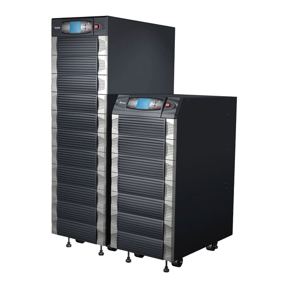
Page 17: General View
3. General View 3-1. Appearance External Battery Pack Power unit LCD Display and Control Panel... -
Page 18: Dimension
3-1-1 Dimension Fig. 3-1 Power Unit (mm) Fig. 3-2 External Battery Pack (mm) 3-2 Function... -
Page 19: Front Panel
-2-1 Front Panel LCD Display and Control Panel LED indicators Power Modules I/P and O/P Protectors 1. LCD Displa y and Control Panel / LED indicators : Display UPS st atus and message Setup parameters and control buttons On/Off UP EPO: Emergency Power Off Please refer to Chapter 6-1 for more det ails. -
Page 20: Function
(2) Parallel link communication (3) Input and Output Dry Contact (4) RS232 : Delta’s software ”UPSentry Smart 2000” or “InsightPower Manager” are optional choice for central monitoring and control purpose) 2. Power Module and wiring: - Remove the cover, you can perform wiring for power modules. -
Page 21: Specification
3-3 p S ecification Table 3-1 Delta NH-series Technical Data Capacity 15kVA/12KW 20kVA/16KW 30kVA/24KW 40kVA/32KW 50kVA/40KW 60kVA/48KW 80kVA/64KW 220/380 , 230/400 , 240/415 ting Voltage ( 3Φ 4W+Earth ) % Volt age regulation -25 ~ +20 ut current harmonic %... -
Page 22: Before Installation
4. Installation 4-1 Before Installation Due to different installation environment, we strongly recommend you to read this manual carefully before installation. Only qualified service personnel can perform installation and maintenance. 4-2 Package Inspections External It’s not predictable that UPS or battery pack will suffer what kind of impact or accident during transportation. -
Page 23: Unpacking Procedure
Charging procedure: Connect UPS to the utility. If external battery pack is ordered, please connect the battery pack to the UPS. Start UPS. At this time, UPS will charge the battery by internal charging circuit. 3. Remain sealed as original packing. Prevent any possible damage from mouse or similar creatures. -
Page 24: Location
4-5 Location 4-5-1 Moving 1. NH-series UPS has casters to roll at a short distance to your desired location. Under unpacking procedure, employ a suitable machine with sufficient capacity to move UPS. Please pay extremely attention when unbolt UPS from shipping pallet. Prevent any accident caused by unexpected moving. -
Page 25: Environment
Table 4-2 Floor Loading for External Battery Pack 40 pcs Capacity (Ah) 12V/26AH Weight (kg) Floor Loading 1064 (kg/㎡) 4-5-3 Environment 1. NH-series is for in-house use only. 2. The installation space should be conditioned at temperature 25 C, related humidity <90%. 3. -
Page 26: Wiring
4-6 Wiring 4-6-1 Preparations: 1. De-energize all input (AC or DC) or output power source of UPS before installing cables or making any electrical connections. 2. Make sure that all cables are correctly marked according to the purpose. Also the polarity, phase and diameter. - Page 27 Wiring procedure: 1. Remove cover at the rear side. See Fig. 4-1 Remover Cover Input Bypass Input External Battery Output Fig. 4-1 Wiring Terminal Grounding Terminal Terminal block (Refer to Fig 4-1): Input / Bypass : Ph-R、S、T and Neutral Output : Ph-R、S、T and Neutral External Battery : Positive(+), Negative(-) and neutral Grounding : Protection 2.
- Page 28 6. Confirm UPS output circuit breaker (Q4) is cut off. 7. According to UPS model you select, using suitable cable and lug (Refer to Table 4-3). 8. Connect all cables to the right terminal or location as indicated (Refer to Fig. 4-1). Q1: Input Circuit Breaker Q2: Bypass Input Circuit Breaker Q3: Manual Bypass Circuit Breaker...
- Page 29 Table 4-3 Input/Output Electrical Data Input Output Input Cable Reserve Reserve Output Output Battery Battery Breaker (mm²) Breaker Cable Breaker Cable Cable Fuse (mm²) (mm²) (mm²) 220/380 220/380 220/380 220/380 220/380 220/380 220/380 220/380 220/380 220/380 220/380 220/380 220/380 220/380 * Please follow the statute according to the installation region, select suitable breaker and cable.
-
Page 30: Wiring (Parallel Redundancy, Single Input)
4-6-3 Wiring (Parallel Redundancy, single input) 1. Confirm input and bypass input breaker (Q1 and Q2) is cut off (Refer to Fig. 4-2). 2. Confirm manual bypass circuit breaker (Q3) is cut off. 3. Confirm output breaker (Q4) is cut off. 4. -
Page 31: Wiring (Parallel Redundancy, Dual Input)
-6-4 Wiring (Parallel Redundancy, dual input) 1. Confirm input and bypass input breaker (Q1 and Q2) is cut off (Refer to Fig. 4-2). 2. Confirm manual bypass circuit breaker (Q3) is cut off. 3. Confirm output breaker (Q4) is cut off. 4. -
Page 32: Interface
-7 Interface Smart Card Slot RS232 PARALLEL OUTPUT DRY CONTACT Parallel RS232 Com. Port Communication Port Input Dry Contact Dry Contact Output Fig. 4-5 Interface -7-1 Input Dry Contact P1:REPO (Remote Emergen cy Power Off) 2:Input contact (Two sets) P3:External Battery Cabinet Temperature 1 P4:External Battery Cabinet Temperature 2 P5:External Battery Cabinet Temperature 3... - Page 33 4. P7 : External Battery Status (Optional) You can order this optional cable to detect the status of external battery cabinet. This function is only for cabinet ordered from DELTA. Pin1:+12V Pin2:Detection cable connected Pin3:Extern al battery cabinet breaker’s status :...
-
Page 34: Output Dry Contact
4-7-2 Output Dry Contact COMM_A +12VS DRYA_NO DRY1 COMM_B +12VS DRYB_NO DRY2 COMM_C +12VS DRYC_NO DRY3 COMM_D +12VS DRYC_NO DRY4 COMM_E +12VS DRYE_NO DRY5 COMM_F +12VS DRYF_NO DRY6 Fig. 4-8 Output Dry Contact Detail 4-13... - Page 35 NH series provide 6 dry contact outputs. These contacts can be setup to normal open or normal close. The default message is: Contact Message Description Pin1-2 Load on inverter UPS is working normally Pin3-4 Load on auto bypass UPS is in bypass mode Pin5-6 Mains1 input fail when Utility is blackout or abnormal.
-
Page 36: Rs232 Port
Use the parallel communication cable within the accessory pack. Link UPS with unsuitable cable may result in accident. 4-7-5 Smart Card Slot NH series provide two smart slots and DELTA develops many powerful smart cards for different applications. 1. SNMP Card (Optional) - Page 37 Features: SNMP agent and web server implemented for UPSSupport the following protocols: ARP, IP, ICMP, SNMPv1, SNMPv3 USM, UDP, TCP, HTTP, FTP, TFTP, SMTP, BOOTP, SNTP, DN and Telnet Security login by MD5 Users level management Firmware upgrade for new features through TFTP Batch configuration through FTP Save UPS event log and history values in EEPROM Schedule shutdown, restart and test UPS...
-
Page 38: Card
2. Programmable Relay I/O Card (Optional) Features: UPS status information presented as 6 contact closuresProgrammable output contacts, monitors the UPS events that users really concern in different application practices Configurable UPS shutdown delay time Configurable input signal as shutdown UPS or battery test Has the ability to protect up to 6 computers unattended shutdown gracefully Technical Spec. - Page 39 I/O Definition GND-R: Relay Grounding Common: 12 ~ 24VDC Default Summary Alarm Input Power Fail Battery Low UPS in Bypass Mode Overload Over Temperature Input : Remote shutdown or battery test Tx: Transmit to PC, connect to RS232 pin-2 Rx: Receive from PC, connect to RS232 pin-3 GND-C: Ground for configuration, connect to RS232 pin-5 OFF(Default) Normal Open...
-
Page 40: Other Optional Accessories
I/O Definition Ground for RS232 RS232-Tx Tx to PC RS232-Rx Rx from PC RS422-T+ T+ for RS422 or RS422-D+ D+ for RS485 RS422-T- T- for RS422 or RS422-D- D- for RS485 RS422-R+ R+ for RS422 RS422-R- R- for RS422 4-8 Other Optional Accessories 1. - Page 41 2. SNMP+ 5 Ports Switching Hub Features: Fast ethernet 5 ports 10/100M smart switching hub SNMP agent and web server implemented for UPS Support the following protocols: ARP, IP, ICMP, SNMPv1, SNMPv3 USM, UDP, TCP, HTTP, FTP, TFTP, SMTP, BOOTP, SNTP, DN and Telnet Security login by MD5 Users level management Firmware upgrade for new features...
-
Page 42: Operating Procedure
5. Operating Procedure 5-1 Start up Procedure (Single Unit) Preliminary Check: All circuit breakers are cut off, including the breaker or fuse of the external battery cabinet. Confirm there is no voltage potential between NEUTRAL and Ground. Confirm the input power source matches the rating (Voltage、frequency、phase and battery ) of UPS you install. -
Page 43: Powering Down (Single)
5-3 Powering Down (Single Unit) This procedure will shutdown UPS and also the output for loads. Confirm all loads are turned off first! Press button ” O ” for 3 seconds until you hear a beep then release button. If originally UPS is in - normal mode : Then UPS will transfer to bypass mode. -
Page 44: Powering Down (Parallel Redundancy)
Start up procedure: 1. Connect two UPS with parallel communication cable. Ensure the connector is fastened to the DB9 port. 2. If there is an external battery cabinet is connected, switch on the breaker of external battery cabinet. 3. Switch on “Q2” of each UPS. The LCD display will show ”ON AUTO BYPASS”. 4. - Page 45 5-7 Manual Bypass Start ups (Parallel Redundancy) Only for maintenance purpose, you can turn on manual bypass switch. If you switch on Q3 under normal condition, then inverter will turn off and output will be supplied by manual bypass source. 5-7-1 Online Mode transfers into Manual Bypass Mode 1.
-
Page 46: Display And Configuration
6. Display and Configuration 6-1. Control Panel Fig. 6-1 Control Panel 1. Normal (Green): Turn on when UPS input power is normal Battery (Amber): Turn on when UPS is in backup mode Bypass (Amber): Turn on when UPS is in manual bypass mode Fault (Red): Turn on when any fault occurs LCD Display: LCD screen, Multi-language (Chinese tradition/Big5, English) 6. -
Page 47: Lcd Display
6-2 LCD Display NH series UPS provide user-friendly LCD screen to show messages. 6-2-1 LCD Display Hierarchy: Level 1 Level 1 Welcome/ Alarm/Fault Info UPS Diagram Level 2 Level 2 Level 2 Measures & UPS Setup Maintenace Status Level 3 Level 3 Level 3 Mains Input... -
Page 48: Default Screen
6-3 Default Screen After UPS starts up and completes the self-test, screen will show: LOAD UNPROTECTED LOAD UNPROTECTED ON AUTO BYPASS ON AUTO BYPASS BYPA. BYPA. MAINS MAINS 1. When any event occurs, you will see the sign “!” flashes. You can press “ ” to see the details. -
Page 49: Status Display
6-3-1 Status Display LCD display will show the different status of UPS: LOAD NOT POWERED BYPA. MAINS This message means: The loads behind UPS are not powered. UPS cuts off the output. Maybe due to: - UPS automatically shutdown by itself. - Manually switch off the output circuit breaker. - Page 50 SOFT START… BYPA. MAINS This message means UPS startup by battery power. LOAD UNPROTECTED LOAD UNPROTECTED ON AUTO BYPASS ON AUTO BYPASS BYPA. BYPA. MAINS MAINS This message means: UPS is in bypass mode. In the mean time, main power source and battery are cut off.
- Page 51 LOAD PROTECTED ONLINE MODE BYPA. MAINS This message means: UPS is operating under normal condition (normal mode). LOAD PROTECTED ON BATTERY / BAT REM: 1123 MIN BYPA. MAINS This message means: UPS is in battery backup mode. Loads are supplied by battery power.
- Page 52 LOAD PROTECTED ON BATTERY / BAT REM: 2 MIN BYPA. MAINS This message means: UPS is in battery backup mode and remaining backup time only 2 minutes left. Battery power is nearly exhausted. LOAD PROTECTED BAT TEST BYPA. MAINS This message means: UPS is performing “battery test”.
- Page 53 LOAD PROTECTED ECO MODE BYPA. MAINS This message means: UPS is in ECO (Economic Operation) mode. Loads are supplied power by bypass source. LOAD UNPROTECTED ON MANUAL BYPASS BYPA. MAINS This message means: UPS is in manual bypass mode. When service personnel performs the maintenance work, UPS must be transferred into this mode first.
-
Page 54: Main Menu
6-4 Main Menu Press “ ” in default screen will change into the main menu: ress “ ” or ” ” to select desired item, then confirm by press “ ”. MEASURE Move cursor by “ ” or ” ” to “Measure”. Select this item by press ” ”... - Page 55 ℃ ℃ ℃ ℃ ℃ ℃ ℃ ℃ 6-10...
-
Page 56: Ups Setup
6-5 UPS SETUP Move c ursor by “ ” or ” ” to “Measure”. Select this item by press ” ” Before get into the “UPS SETUP”, you have to login first: 1. The login screen is as right. Move cursor to select your correct ID, then press ”... -
Page 57: A. Bypass Setup
a. BYPASS SETUP Move cursor by “ ” or ” ” to “BYPASS SETUP”. Select this item by press ” ” 1. Move cursor by “ ” or ” ” to select “VOLTAGE RANGE” or “FREQUENCY RANGE”. Press ” ” to confirm the choice. 2. -
Page 58: B. Output Setup
b. OUTPUT SETUP Move cursor by “ ” or ” ” to “OUTPUT SETUP”. Select this item by press ” ” All the parameter in this segment can only be changed under “Bypass Mode”. 1. Move cursor by “ ” or ” ” to select the desired item. -
Page 59: C. Battery Setup
c. BATTERY SETUP Move cursor by “ ” or ” ” to “BATTERY SETUP”. Select this item by press ” ” All the parameters in this segment can only be changed under “Bypass Mode”. 1. Move cursor by “ ” or ” ” to select the desired item. -
Page 60: D. Local Setup
d. LOCAL SETUP Move cursor by “ ” or ” ” to “LOCAL SETUP”. Select this item by press ” ” 1. Move cursor by “ ” or ” ” to select the desired item. Press ” ” to confirm the choice. 2. - Page 61 5. Move cursor by “ ” or ” ” to setup the audible alarm. Press ” ” to confirm the choice. 6. Move cursor by “ ” or ” ” to s etup the contrast of LCD screen. Press ” ”...
-
Page 62: Maintenance
6-6 Maintenance e cursor “ ” or ” ” to the ”MAINTENANCE” in the main menu, confir by press “ ”. 1. Move cursor by “ ” or ” ” to select the desired item. & & Press ” ” to confirm the choice. 2. - Page 63 2. Move cursor by “ ” or ” ” to select the desired item. Press ” ” to confirm the choice. EVENT LOG EVENT LOG Event log example 07-07-03 13:17:00 07-07-03 13:17:00 UPS State:Load on Inverter UPS State:Load on Inverter 07-07-03 13:15:57 07-07-03 13:15:57 Input Voltage Normal Input Voltage Normal 07-07-03 13:15:57 07-07-03 13:15:57 Input Frequency Normal Input Frequency Normal 07-07-02 13:15:54 07-07-02 13:15:54 UPS State: Load on Bypass...
- Page 64 Press “ ” to execute “MANUAL ATTERY TEST”. (This item is only accessible for dministra r. Password will be nfirmed gain!) Press “ ” to execu te “BUZZER AND ED TEST”. (This item is only accessible for administrator! Password will be confirmed again!) Press “...
-
Page 65: Power Management Software
7. Power Management Software 7-1 DELTA Software Family Communication Port RS232 RS485 SNMP ◆ InsightPower Client ◆ ◆ UPSentry Smart 2000 ◆ ◆ ◆ InsightPower Manager ◆ Shutdown Agent Application Shutdown OSCentralized Management Remote Monitoring ◆ ◆ InsightPower Client ◆... -
Page 66: Upsentry Smart 2000
7-2 UPSentry Smart 2000 DELTA develops a power software family to easily integrate UPS into your system. “UPSentry Smart 2000” supports all popular OS such as Windows, Linux, FreeBSD …etc. Advanced Features: Supports RS232 and USB protocols Multi-lingual design (English, French, German, Spanish, Portuguese, Italian, Polish,... -
Page 67: Flexible Management Tools
7-2-1 Flexible Management Tools “UPSentry Smart 2000” provides powerful tools for administrator of data center, MIS, IDC. 1. Real-Time Monitoring, record and analysis Real-Time meters: 4 ( single phase ) or 12 ( 3 phases ) meters. Each meter is user-defined to display power information (voltage, current, frequency…) or UPS’s status. - Page 68 Shutdown OS Event Log Transmit an Execute External Popup audible message Command Message . Overload Warning Setup Administrator can setup tw o stage of overload limit between 0%-100%. Warning message will popup when reach the loading limit. 4. Scheduled Shutdown/Auto Restart UPSentry Smart 2000 can perform OS shutdown process before UPS turns off.
-
Page 69: Insightpower Manager
7-3 InsightPower Manager For data center or large scale factory, administrator need a convenient tool to centrally control and monitor UPSs. DELTA develops “InsightPower Manager” to achieve this purpose. Features: Centralized UPS management system via TCP/IP network Supports RS232, RS485 and... - Page 70 Event Log: Record events and operation by date/time Generate historical report and can be transferred into EXCEL file Setup a periodically analyzing report. Network InsightPower InsightPower Manager Service Manager Monitor SNMP SNMP RS232/485 SNMP RS232/485 InsightPower Manager Monitor Remote UPS Monitoring...
Need help?
Do you have a question about the NH-20k and is the answer not in the manual?
Questions and answers