
Related Manuals for GLP impression XL


Summary of Contents for GLP impression XL
- Page 1 Instruction Manual from Software Version 1.09/0.3 (Manual Version 1.04) e-mail: service@glp.de Internet: http://www.glp.de...
- Page 2 For your notes: German Light Products GmbH (Manual Version 1.04) / from Software Version 1.09/0.3)
-
Page 3: Table Of Contents
Table of content Description of Device ......................4 Safety Instructions ........................5 Preparation and Installation....................6 Mounting ............................6 2.1.1 Mounting on the Floor (Upright) ..................7 2.1.2 Mounting in hanging Position (Head first) ...............7 2.1.3 Mounting in sidewise Position ..................8 Secure the Device ........................9 Connections ..........................9 2.3.1 Power Supply ........................9... -
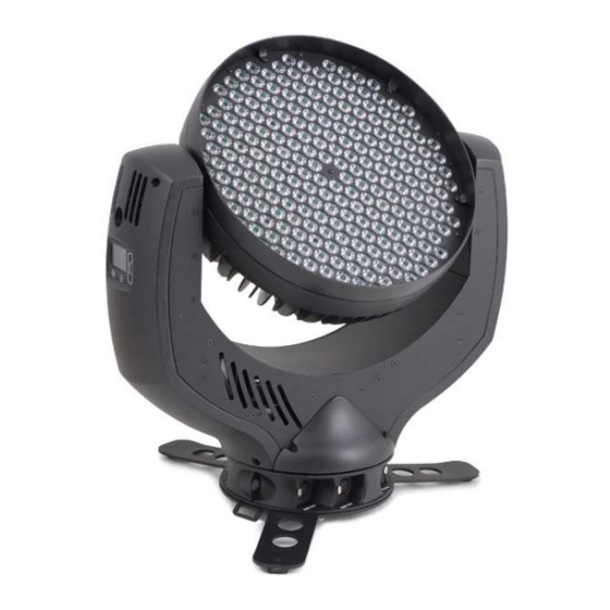
Page 4: Description Of Device
1 Description of Device 1. Moving head (actively and passively cooled) 2. Arm with various cooling vents 3. Tilt-lock to secure and lock the tilt movement see also 1.1 Safety Instructions 4. LCD-Display/Menu (data entry) 5. Base with various connectors and Camlock mounting system Safety eyelets... -
Page 5: Safety Instructions
Safety Instructions L is a High-Tech Product. To guarantee a smooth operation, it is necessary to respect the following rules. The manufacturer of this device will not take responsibility of damages through any disregard of the information in this manual. Warranty claims also will be cancelled in case the system casing is opened. -
Page 6: Preparation And Installation
Safety cables or clamps/hooks can increase the risk of an accident. 10. Repair-, maintenance- and installation work shall be done by qualified or GLP certified staff only. You need to pay attention to the common rules of technology that are not explicit mentioned in this manual. -
Page 7: Mounting On The Floor (Upright)
Pay attention to the regulations of: BGV C1 (former VBG 70) and DIN VDE 0711-217. The installation shall be done by qualified staff only. For the various mounting positions of the L (standing on the floor, sideways or hanging) different accessories kits are available. Through this a safe and firm installation is assured. -
Page 8: Mounting In Sidewise Position
half-couplers (clamp) which need to be mounted to the camlock brackets. 2.1.3 Mounting in sidewise Position To operate the L in a sidewise position, please use an addition mounting bar. Also this is fixed by two Camlock quick-release connectors. Two half-couplers (clamps) are now used to mount the system to a standard truss bar. -
Page 9: Secure The Device
2.2 Secure the Device Regardless of the mounting method of the L you'll have to use a stipulated safety wire. Therefore you have to pull the safety wire through at least one of the two provided flat eyelets on the base of the system and connect it with the truss-support. -
Page 10: The Menu Field
3 The Menu Field You’ll find the control board on the side part of the arm. It allows you to make all necessary adjustments of the . With the Mode-key you set into the main menu. Afterwards you can navigate through the menu with the scroll-wheel. Push the Enter-key to get in the next menu level or to confirm your settings. - Page 11 Tilt Offset Calibration for Tilt-Offset Clear Erase EEPROM memory EEPROM Diagnose Diagnose functions Pos Feed Pan Internal data and function diagnose Delta Anz Ti0-Int- Internal data and function diagnose PFC Voltage Show the present PFC voltage LED PWM Shows Dimmer-1-Software Version Vers 1 LED PWM Shows Dimmer-2-Software Version...
-
Page 12: Dmx Channel Sheet
Shutter Instantaneous value for Shutter Blue Instantaneous value for Blue Green Instantaneous value for Green Instantaneous value for Red Color Wheel Instantaneous value for Color Mixing unit Tilt Instantaneous value for Tilt movement Indicates the overall operation time of the Live time system Display... - Page 13 Channel Function Time and Value Color 10 - Mauve 80..87 50..57 31..34,5 Color 11 - Magenta 88..95 58..5F 35..37,5 Color 12 - Pink 96..103 60..67 38..40,5 White - CTO Color temperature 104..111 68..6F 41..43,5 3200K White Color temperature 112..119 70..77 44..46,5 5600K White - CTB...
- Page 14 Channel Function Time and Value TILT size / phase see also PAN 32..63 20..3F 13..25 PAN / TILT size / phase see also PAN 64..95 40..5F 26..37 PAN / TILT (inverse) size / phase see also PAN 96..127 60..7F 38..50 Circle size / phase see also PAN 128..159...
- Page 15 Channel Function Time and Value Color 09 - Lavender 72..79 48..4F 28..30,5 Color 10 - Mauve 80..87 50..57 31..34,5 Color 11 - Magenta 88..95 58..5F 35..37,5 Color 12 - Pink 96..103 60..67 38..40,5 White - CTO Color temperature 104..111 68..6F 41..43,5 3200K White...
- Page 16 Channel Function Time and Value 11) Shutter Shutter closed 0..15 00..0F 0..5,5 Random Pulse effect slow - fast 16..47 10..2F 6..18,5 Up-dimming then Shutter closing slow - fast 48..79 30..4F 19..31,5 (random patterns) Shutter open then down-dimming slow - fast 80..111 50..6F 32..43...
-
Page 17: Maintaining And Cleaning The I M P R E S S I O N X L
5 Maintaining and Cleaning the L is a system of very low maintenance. It is only necessary to clean the air in- and outlets as well as the optical LED lenses from time to time. For a safe operation it is absolutely essential that the fixture is kept clean and that dust, dirt and smoke-fluid residues must not built up on or within the fixture. -
Page 18: Technical Specifications
6 Technical Specifications Power supply Power consumption 1200 VA (Watt) Power Input ~100-240 V AC, 50-60 Hz (wide range input) Fuse protection Micro-fuse 6.3x32 mm, T15A Operational Parameters Max. Ambient 45° C (integrated overheating switch) Temperature Mounting Position Any (see chapter mounting) Lighting System - Additive Color mixing LED Type 240x Luxeon K2 High-power- LEDs... -
Page 19: Index
7 Index Menu Field ............ 10 Micro-fuse ............9 BGI 810-3 ............9 Mode-key ............ 10 BGV C1............7 Mounting ............6 Mounting in hanging Position ......7 Mounting in sidewise Position ......8 Camlock ............7 Mounting on the Floor ........7 Circumference .......... - Page 20 German Light Products GmbH (Manual Version 1.04) / from Software Version 1.09/0.3)
Need help?
Do you have a question about the impression XL and is the answer not in the manual?
Questions and answers