Advertisement
Table of Contents
- 1 Table of Contents
- 2 General Specifications
- 3 Installation Requirements
- 4 Electrical Connection
- 5 Set up Utilizing Bluetooth App
- 6 Set up Using Buttons and Display on Valve
- 7 Master Programming
- 8 Control Valve Power Assembly
- 9 Valve Body Assembly
- 10 Tank Assembly
- 11 Bypass Assembly
- 12 Service Instructions
- 13 Troubleshooting
- 14 Error Codes
- 15 Warranty
- Download this manual
Advertisement
Table of Contents

Related Manuals for CSI SK25


Summary of Contents for CSI SK25
- Page 1 Signature 3 Installation / Operation Manual...
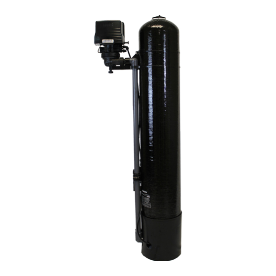
- Page 2 ABOUT YOUR SYSTEM The Sidekick uses the air we breath to naturally reduce the effects of Iron, Manganese and Sulfur Gas. By introduc- ing oxygen to the water, contaminants chemically change to a physical particle that can be mechanically filtered out of this water.
-
Page 3: Table Of Contents
General Specifications................... Page 4 Installation Requirements................Page 5 Electrical Connection..................Page 7 Set Up Utilizing Bluetooth App ..............Page 8 Set Up Using Buttons and Display on Valve..........Page 11 Master Programming..................Page 14 Control Valve Power Assembly..............Page 16 Valve Body Assembly.................. -
Page 4: General Specifications
Specifications General Specifications SK15 SK25 Smart Blend 1.5 cu. ft. 2.5 cu. ft. Gravel Underbedding 20 lbs. 50 lbs. Mineral Tank 10 X 54 13 X 54 Service Flow Rate - Continuous (GPM) Service Flow Rate - Intermittent (GPM) Backwash Flow Rate (GPM) -
Page 5: Installation Requirements
Installation Installation Requirements Make sure you have level floor position ahead of piping into water heater. Unit must be installed at least 10 feet ahead of the inlet to a water heater to prevent damage due to back-up hot water. DO NOT install the unit in an area of direct sunlight or where freezing temperatures may occur! Locate the unit near an unswitched, 120 volt / 60 Hz grounded electrical outlet. - Page 6 Installation Installation Procedure - Water Supply Connection and Bypass Valve - To allow for filter servicing, swimming pool filling or lawn sprinkling, a manual Bypass Valve has been installed at the factory. The Bypass allows raw water to be manually routed around the filter. 1.
-
Page 7: Electrical Connection
Installation - Electrical Connection - Connect the power cord and plug power supply into a 115 volt / 60 Hz receptacle. Note : Do not plug into an outlet controlled by a wall switch or pull chain that could inadvertently be turned off Electronic Connections P = Power Supply B = Powered in Air Replenish Step Only... -
Page 8: Set Up Utilizing Bluetooth App
Set Up Utilizing Bluetooth App For simplified set up and control, please install the Legacy View on a compatible Bluetooth 4.0+ (BTLE) enabled smart phone or tablet. 1. Download and install the Legacy View app from the Google Play Store, Apple App Store 2. - Page 9 Set Up Utilizing Bluetooth App 1. Change Time of day (Press “set” to set time automatically based on device time) 1. Set Backwash Frequency This sets the amount of days between backwash cycles. 1. Set Regeneration Time Example: For 2am, just type 2 and press OK. Advanced Settings NOTE: Consult your dealer before making any changes.
- Page 10 Set Up Utilizing Bluetooth App Status and History From the Status and History, all items in ORANGE can be reset. Touch any table to explode a detailed list of the last log data Start a regeneration or backwash cycle Option 1: Click the “Regenerate Unit Now.”...
-
Page 11: Set Up Using Buttons And Display On Valve
Set Up Using Buttons and Display on Valve Setting Up and Controlling the System Using the Buttons on the Valve Main Menu 12:00 1. To enter Main Menu, press the Menu/Enter button. (Time of Day will flash) 2. To set the Time of Day, press the Set/Change button. (First digit will flash) Example [12:00] To change digit value, press the Set/Change button. - Page 12 Set Up Using Buttons and Display on Valve Normal Operation 1. Home Display a. Alternates between the display of Time of Day and Number of Days until the Next Backwash. - Days Remaining until the Next Backwash will count down from the entered value until it reaches 1 day remaining.
- Page 13 Set Up Using Buttons and Display on Valve Sidekick Backwash Cycle Step Explanations Step 1: Air Release Step -For approximately 6 minutes, Non-adjustable This position slowly opens the treatment tank to the drain. This allows air in the top of the tank to be gently released out the drain.
-
Page 14: Master Programming
Master Programming Mode Master Programming Mode To enter Master Programming Mode, press and hold both buttons for 5 seconds. Note: All Master Programming functions have been preset at the factory. Unless a change is desired, it is NOT necessary to enter Master Programming Mode. 1. - Page 15 Master Programming Mode Notes: - If the pulse chlorine setting is on (1-4) the minimum time for the Air Replenish/Oxyclean NP Injection cycle step is forced to 20 minutes. - If the pulse chlorine setting is set to 4 the minimum time for the Rapid Rinse cycle step is forced to a minimum of 5 minutes.
-
Page 16: Control Valve Power Assembly
Control Valve Powerhead Assembly LETTERS IN DIAGRAM REPRESENT WIRING CONNECTIONS... - Page 17 Control Valve Powerhead Assembly Description Part Number Powerhead Assy. 20015X100 Circuit Board Assy. 20015X101 Encoder 20001X124 Front Plate 20001X004 Encoder Wheel 20001X007 Main Gear 21001X120 Power Supply 20001X125 Back Plate 20001X005 Lower Front Base For Cover 20111X002 Microswitch 20251X113 Switch Spacer 20111X004 Brine Motor Mount 20111X006...
-
Page 18: Valve Body Assembly
Sidekick Valve Body Assembly AIR INJECTION ASSEMBLY (Located near base of tank) To Air Injection Assembly... - Page 19 Sidekick Valve Body Assembly Description Part No. Piston Assembly Final Rinse 20009X231 10-24 X 13/16 Hex Head 20001X226 Seal and Spacer Kit 20561X253 Bottom Spacer DLFC 5.0 Button 20251X272 DLFC 7.0 Button 20251X273 Flow Control Assembly 5.0 20017X262 Flow Control Assembly 7.0 20017X264 Drain Line Flow Control (DLFC) 22001X100...
-
Page 20: Tank Assembly
Tank Assembly... - Page 21 Tank Assembly Description Part No. Tank Cap Q-7004 Tank Distributor Tube (per foot) 33012X001 10” Black Tank 31054X000 13” Black Tank 31354X000 10” Zip Tie 13” Zip Tie Tank Bracket 20015X011 Basket 33000X003 Tank Adapter 20015X008 13” Tank Extension 20015X002 Requires one of 20561X205 also Sidekick Nut 20015X007...
-
Page 22: Bypass Assembly
Bypass Assembly Description Part No. D15 Bypass 20017X283 1” Female Straight Slip Set 20017X288 1” NPT Elbow Set 20017X284 1” NPT Straight Set 20017X289 Elbow, Vertical Adapter 20017X295 Blank Elbow, Vertical Adapter 20017X294 1/4” NPT Tapped... -
Page 23: Service Instructions
Service Instructions / Instructional Videos Available at www.csiwater.com General Preliminary Instructions PERFORM BEFORE ALL SERVICING OPERATIONS 1. Turn off water supply to conditioner. -If the conditioner installation has a “three valve” bypass system, first open the valve in the bypass line, then close the valves at the conditioner inlet and outlet. - Page 24 Service Instructions / Instructional Videos Available at www.clearionwater.com To Replace Meter 1. Follow steps A1 - A3 2. Unplug meter cable from front of circuit board. 3. Unscrew meter assembly nut from valve body. 4. Remove meter from valve body and clean or replace as necessary. 5.
-
Page 25: Troubleshooting
Troubleshooting Guide SYMPTOM PROBABLE CAUSE CORRECTION Power supply plugged into Connect to constant power source intermittent or dead power source 1. Fails to Regenerate Improper control valve Reset program settings Automatically programming Defective power supply Replace power supply Defective Drive motor Replace motor 2. -
Page 26: Error Codes
Error Codes Control Valve Error Code Diagnosis Under normal operating conditions, when your control valve is in the “in service” position, the display should alternate between the current time of day and the number of days remaining (for filters and time clock softeners) or gallons remaining (for metered softeners) until the next regeneration. -
Page 27: Warranty
Brine Tank Components 1 Year the price paid for the product. In no case shall CSI or seller be liable for REVERE Wireless Low Salt Alarm 90 Days any special, incidental, contingent or consequential damages. Special, incidental, contingent and consequential damages for which CSI is not * This warranty does not include media and/or cartridge filter elements. - Page 28 CSI WATER TREATMENT SYSTEMS 710 Orange St, Ashland, OH 44805 l PH 419-281-6829 l FAX 419-281-2375 1/17TV...
Need help?
Do you have a question about the SK25 and is the answer not in the manual?
Questions and answers