Table of Contents
Advertisement
Quick Links
Advertisement
Table of Contents

Related Manuals for CSI signature 2 SK15


Summary of Contents for CSI signature 2 SK15
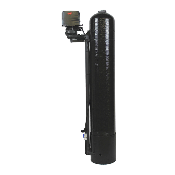
- Page 1 SIGNATURE 2 Signature 2 Installation / Operation Manual...
-
Page 2: Table Of Contents
SIGNATURE 2 Specifications..................Page 2 Installation Requirements..............Page 3 Electrical Connection................Page 5 Control Start-Up Procedures..............Page 6 Master Programming................Page 11 Utilizing Bluetooth..................Page 12 Control Valve Power Assembly.............Page 13 Valve Body Assembly................Page 14 Tank Assembly..................Page 15 Additional Information................Page 16 Troubleshooting..................Page 18 WARNING Lubricants Do NOT use Vaseline, oils, hydrocarbon lubricants or spray silicone anywhere! Petroleum base lubricants will cause swelling of o-rings and seals. -
Page 3: Signature
SIGNATURE 2 Specifications General Specifications SK15 SK25 Smart Blend 1.5 cu. ft. 2.5 cu. ft. Gravel Underbedding 20 lbs. 50 lbs. Mineral Tank 10 X 54 13 X 54 Service Flow Rate - Continuous (GPM) Service Flow Rate - Intermittent (GPM) Backwash Flow Rate (GPM) Gallons Used / Backwash Space Required (D x W x H inches) -
Page 4: Installation Requirements
SIGNATURE 2 Installation Installation Requirements Make sure you have level floor position ahead of piping into water heater. Unit must be installed at least 10 feet ahead of the inlet to a water heater to prevent damage due to back-up hot water. -
Page 5: Electrical Connection
SIGNATURE 2 Electrical Connection Installation Procedure - Water Supply Connection and Bypass Valve - To allow for filter servicing, swimming pool filling or lawn sprinkling, a manual Bypass Valve has been installed at the factory. The Bypass allows raw water to be manually routed around the filter. Position filter at desired location for installation. - Page 6 SIGNATURE 2 Electrical Connection - Electrical Connection - Connect the power cord and plug power supply into a 115 volt / 60 Hz receptacle. Note : Do not plug into an outlet controlled by a wall switch or pull chain that could inadvertently be turned off Electronic Connections P = Power Supply B = Powered in Air Replenish Cycle Only...
-
Page 7: Control Start-Up Procedures
SIGNATURE 2 Control Start-Up Procedures Main Menu 12:00 1. To enter Main Menu, press the Menu/Enter button. (Time of Day will flash) 2. To set the Time of Day, press the Set/Change button. (First digit will flash) Example [12:00] To change digit value, press the Set/Change button. To accept the digit value, press the Menu/Enter button. -
Page 8: Normal Operation
SIGNATURE 2 Control Start-Up Procedures Normal Operation Home Display a. Alternates between the display of Time of Day and Number of Days until the Next Backwash. - Days Remaining until the Next Backwash will count down from the entered value until it reaches 1 day remaining. - Page 9 SIGNATURE 2 Control Start-Up Procedures Default (Min) Step 1 Air Release Step 2 Oxyclean NP Injection 15 sec Step 3 Short Rinse Step 4 Rest Steps 1-4 are non-adjustable Step 5 Backwash Step 6 Rest Step 7 Air Replenish (Optional O Step 8 Rapid Rinse...
- Page 10 SIGNATURE 2 Control Start-Up Procedures Sidekick Backwash Cycle Step Explanations Step 1: Air Release Step For approximately 6 minutes - Non-adjustable Step 2: Oxyclean NP Injection For 15 seconds - Non-adjustable Step 3: Short Rinse Step For 1 minute - Non-adjustable Step 4: Rest Step For 20 minutes...
- Page 11 SIGNATURE 2 Control Start-Up Procedures Note: Depending upon system pressure and other factors, it is possible to observe flow to drain in the rest cycles. - When the valve is between positions, the display will flash the number of the step it is moving towards.
-
Page 12: Master Programming Mode
SIGNATURE 2 Master Programming Mode Master Programming Mode To enter Master Programming Mode, press and hold both buttons for 5 seconds. Note: All Master Programming functions have been preset at the factory. Unless a change is desired, it is NOT necessary to enter Master Programming Mode. -
Page 13: Utilizing Bluetooth
SIGNATURE 2 Utilizing Bluetooth Control To take advantage of the Bluetooth interface this feature must be set up on a compatible Bluetooth enabled smart phones or tablets. Note: Valves with a revision number greater or equal to “C2.00” are only compatible with Bluetooth 4.0+ (a.k.a. Bluetooth LE) Smartphones and tablets. - Page 14 SIGNATURE 2 Control Valve Powerhead Assembly LETTERS IN DIAGRAM REPRESENT WIRING CONNECTIONS...
- Page 15 SIGNATURE 2 Description Part Number Powerhead Assy. 20015X100 Circuit Board Assy. 20015X101 Encoder 20001X124 Front Plate 20001X004 Encoder Wheel 20001X007 Main Gear 20001X120 Power Supply 20001X125 Back Plate 20001X005 Lower Front Base For Cover 20111X002 Microswitch 20251X113 Switch Spacer 20111X004 Brine Motor Mount 20111X006 Motor Assembly...
-
Page 16: Valve Body Assembly
SIGNATURE 2 Sidekick Valve Body Assembly AIR INJECTION ASSEMBLY (Located near base of tank) - Page 17 SIGNATURE 2 Description Part No. Piston Assembly 20009X231 10-24 X 13/16 Hex Head 20001X226 Seal and Spacer Kit 20561X253 End Spacer DLFC 5.0 Button 20251X272 DLFC 7.0 Button 20251X273 Flow Control Assembly 5.0 20251X262 Flow Control Assembly 7.0 20251X264 Drain Line Flow Control Housing 20251X100 Drain Line Hose Barb 20251X255...
-
Page 18: Tank Assembly
SIGNATURE 2 Tank Assembly To Injector Cap 4A/B 15A (10"), 15B (13") 15B (10") 18 (13") - Page 19 SIGNATURE 2 Description Part No. Tank Cap Q-7004 Tank Distributor Tube (per foot) 33012X001 10” Black Tank 31054X000 13” Black Tank 31354X000 10” Zip Tie 13” Zip Tie Tank Bracket 20015X011 Basket 33000X003 Tank Adapter 20015X008 13” Tank Extension 20015X002 Requires one of 20001X215 also Sidekick Nut 20015X007...
- Page 20 SIGNATURE 2 Service Instructions / Instructional Videos Available at www.csiwater.com General Preliminary Instructions PERFORM BEFORE ALL SERVICING OPERATIONS 1. Turn off water supply to filter. -If the filter installation has a “three valve” bypass system, first open the valve in the bypass line, then close the valves at the conditioner inlet and outlet.
- Page 21 SIGNATURE 2 Service Instructions / Instructional Videos Available at www.csiwater.com To Replace Injectors & Screen 1. Follow steps A1 - A3 (above) 2. Remove injector cap screws and remove cap. 3. Disassemble and clean air injection assembly (#30) and replace injector (#19) 4.
-
Page 22: Troubleshooting
SIGNATURE 2 Troubleshooting Guide SYMPTOM PROBABLE CAUSE CORRECTION Power supply plugged into Connect to constant power source intermittent or dead power source 1.Fails to Regenerate Improper control valve Reset program settings Automatically programming Defective power supply Replace power supply Defective Drive motor Replace motor 2. -
Page 23: Warning
Brine Tank Components 1 Year the price paid for the product. In no case shall CSI or seller be liable for REVERE Wireless Low Salt Alarm 90 Days any special, incidental, contingent or consequential damages. Special, incidental, contingent and consequential damages for which CSI is not * This warranty does not include media and/or cartridge filter elements. - Page 24 SIGNATURE 2 CSI WATER TREATMENT SYSTEMS 710 Orange St, Ashland, OH 44805 l PH 419-281-6829 l FAX 419-281-2375 www.csiwater.com...
Need help?
Do you have a question about the signature 2 SK15 and is the answer not in the manual?
Questions and answers