Table of Contents
Advertisement
Quick Links
Advertisement
Table of Contents

Subscribe to Our Youtube Channel
Related Manuals for Digitus 15019-2


Summary of Contents for Digitus 15019-2
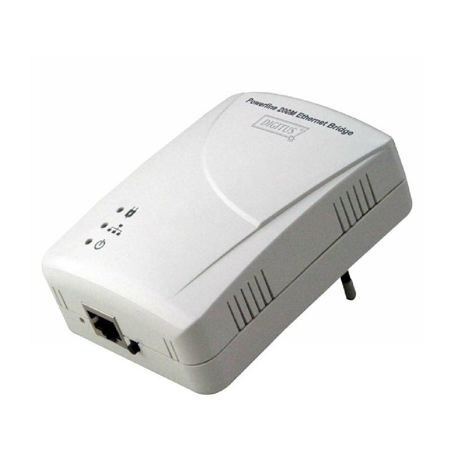
- Page 1 Powerline Ethernet Bridge User’s Manual (D N -15019-2)
-
Page 2: Table Of Contents
Index 1. P ower l ine N etwor king Instal l ation ..........................2 1.1 S impl e step to instal l P ower l ine N etwor king ..................2 1.2 A ppl ication B l ock D iagr am ........................3 1.3 B enefits .............................. -
Page 3: Powerline Networking Installation
1. Powerline Networking Installation 1.1 Simple step to install Powerline Networking... -
Page 4: Application Block Diagram
1.2 Application Block Diagram 1.2.1 Internet ADSL with one computer via power outlet 1.2.2 Online game via power outlet... - Page 5 1.2.3 Internet ADSL and Home Networking via power outlet...
-
Page 6: Benefits
1.3 Benefits ‧D ata tr ansfer s at up to 200 Mbps over the househol d power cir cuit ‧R anges of 200 meter s ‧N o need new wir es for H ome networ king ‧D el iver the benefits of E ther net without the wir ing expense ‧S end even l ar ge fil es between P C s without l ong waits ‧H igh-speed Inter net and D V D -qual ity video str eaming ‧Ful l y compl iant with IE E E 802.3, IE E E 802.3u... -
Page 7: Led Definitions
1.6 LED Definitions State Description P ower l ine networ k activity. Powerline O FF S ear ch or no P ower l ine networ k activity. E ther net connection is O K . Fl ashing D ata tr ansfer . Ethernet O FF N o l ink to E ther net. -
Page 8: Powerline Networking Utility
2. Powerline Networking Utility Note The P ower l ine D evice can auto detect the other P ower l ine br idges which pl ug in the same power cir cuit, you don’ t need to use this P ower l ine util ity except you want to encr yption al l the P ower l ine devices as the same gr oup or you can not access the other computer s. - Page 9 Figure 2.1.1. Figure 2.1.2.
- Page 10 Common Features of Tabbed Windows Status Bar The status bar , al ong the bottom of each window , contains five fiel ds that pr ovide impor tant networ k infor mation. • The fir st fiel d contains the status of the D evice Manager in r espect to connection to a P ower l ine device. ‘...
-
Page 11: User Interface - Network Information Tab
2.1 User Interface - Network Information Tab This window is an O per ation A nal ysis window that r eveal s N etwor k infor mation in thr ee categor ies: C C o Infor mation, C onnected S TA Infor mation and Topol ogy. 2.1.1. -
Page 12: User Interface - Encryption Tab
2.2 User Interface - Encryption Tab This E ncr yption window is used to set or change the networ k passwor d on a r emote device identified by its D A K passwor d. C l icking the ‘ S et’ button sets the enter ed passwor ds. If the D A K passwor d fiel d is l eft bl ank, then cl icking the ‘... -
Page 13: User Interface - Link Information Tab
2.3 User Interface - Link Information Tab 2.3.1. Link Characteristics Box The context of the l ink is identified with the S our ce and D estination addr ess boxes in the Link C har acter istics gr oup box. The S our ce A ddr ess defaul ts to the addr ess of the device sel ected in the D evice S el ection box on the l ower l eft of the tab and the D estination A ddr ess is sel ected fr om a dr op down l ist. -
Page 14: User Interface - Connection Information Tab
2.4 User Interface - Connection Information Tab The C onnection Infor mation window is used to acquir e statistics for both tr ansmit and r eceive oper ations in the l ocal or r emote networ k. 2.4.1. Connection Select CSMA : the D estination A ddr ess (D A ) dr op-down menu may be used to sel ect A LL devices or specific devices in the networ k. - Page 15 Figure 4: Connection Information Tab...
-
Page 16: User Interface - Qos Tab
2.5 User Interface - QoS Tab Q oS r equir ements ar e differ ent for var ious data types such as str eaming video or music, voice and r aw data. To pr ovide higher Q oS for str eaming data, pr ior ity l evel s can be set using tags at the beginning of data fr ames. V ir tual Local A r ea N etwor k (V LA N ) 802.1p pr ior ity tags on E ther net fr ames ar e used to specify 8 (0 –... - Page 17 2.5.3 Default CAP The ‘ D efaul t C A P ’ gr oup al l ows for defaul t pr ior ity mapping of packets that do not have a V LA N or TO S bit (or if these ar e disabl ed).
- Page 18 2.5.4. IGMP The ‘ IG MP ’ gr oup incl udes contr ol s to disabl e the quer y timeouts. C hecking the ‘ O ver r ide D efaul ts’ box wil l enabl e the other boxes as choices. 2.5.5.
-
Page 19: Push Button Setting
3. Push Button Setting Ther e ar e 2 buttons in this device, one is R eset button the other is S ecur e button. Reset: P ush this button can r eset to the factor y defaul t settings. Be careful, when you press the reset button, please make sure unplug (remove) the Ethernet cable (RJ-45cable) first, and then press the reset button. - Page 20 Possible Use Case Scenario 1: Unassociated device joining existing AVLN Possible Use Case Scenario 2: Two devices joining to form new AVLN Before this scenario begin, please make sure to press each device secure button > 10 sec till all LEDs re-flash to generate the random network password key first.
-
Page 22: Trouble Shooting
4. Trouble Shooting 1. Why my utility can not work properly after finish install steps? A ns: P l ease fol l ow the steps to check the pr obl em. C heck the C ontr ol panel for Micr osoft .N E T Fr amewor k instal l status, if you don’ t instal l this, pl ease instal l it.
Need help?
Do you have a question about the 15019-2 and is the answer not in the manual?
Questions and answers