Omron NX701-1700 User Manual
Machine automation controller
nx-series
Hide thumbs
Also See for NX701-1700:
- User manual (168 pages) ,
- Quick start manual (12 pages) ,
- User manual (164 pages)

Related Manuals for Omron NX701-1700


Summary of Contents for Omron NX701-1700
- Page 1 Machine Automation Controller NX-series CPU Unit Hardware User’s Manual NX701-1 NX-PA9001/PD7001 CPU Unit Power Supply Unit W535-E1-07...
- Page 2 No patent liability is assumed with respect to the use of the information contained herein. Moreover, because OMRON is constantly striving to improve its high-quality products, the information contained in this manual is subject to change without notice. Every precaution has been taken in the preparation of this manual. Neverthe- less, OMRON assumes no responsibility for errors or omissions.
-
Page 3: Introduction
Introduction Introduction Thank you for purchasing an NX-series NX701 CPU Unit. This manual contains information that is necessary to use the NX-series NX701 CPU Unit. Please read this manual and make sure you understand the functionality and performance of the NX-series CPU Unit before you attempt to use it in a control system. -
Page 4: Table Of Contents
CONTENTS CONTENTS Introduction ......................1 Intended Audience............................1 Applicable Products ............................. 1 CONTENTS........................ 2 Relevant Manuals ..................... 5 Manual Structure ...................... 6 Page Structure ............................. 6 Special Information ............................7 Precaution on Terminology .......................... 7 Terms and Conditions Agreement ................8 Warranty, Limitations of Liability ........................ -
Page 5: Contents
CONTENTS 1-3-2 Procedure Details ........................1-14 Section 2 System Configuration Basic System Configuration....................2-2 2-1-1 EtherCAT Network Configuration....................2-3 Connecting to the Sysmac Studio ..................2-5 Network Configuration......................2-6 Section 3 Configuration Units CPU Units ..........................3-2 3-1-1 Models and Specifications ......................3-2 3-1-2 Part Names and Functions ...................... - Page 6 CONTENTS Section 5 Troubleshooting Operation after an Error ......................5-2 5-1-1 Overview of NX-series Status ..................... 5-2 5-1-2 Fatal Errors in the CPU Unit......................5-3 5-1-3 Non-fatal Errors in the CPU Unit ....................5-4 Troubleshooting ........................5-11 5-2-1 Checking to See If the CPU Unit Is Operating ................5-11 5-2-2 Troubleshooting Flowchart for Non-fatal Errors ................
-
Page 7: Relevant Manuals
Relevant Manuals Relevant Manuals The following table provides the relevant manuals for the NX-series CPU Units. Read all of the manuals that are relevant to your system configuration and application before you use the NX-series CPU Unit. Most operations are performed from the Sysmac Studio Automation Software. Refer to the Sysmac Stu- dio Version 1 Operation Manual (Cat. -
Page 8: Manual Structure
Manual Structure Manual Structure Page Structure The following page structure is used in this manual. Level 1 heading 4 Installation and Wiring Level 2 heading Mounting Units Level 3 heading Level 2 heading Gives the current headings. Level 3 heading 4-3-1 Connecting Controller Components The Units that make up an NJ-series Controller can be connected simply by pressing the Units together... -
Page 9: Special Information
Manual Structure Special Information Special information in this manual is classified as follows: Precautions for Safe Use Precautions on what to do and what not to do to ensure safe usage of the product. Precautions for Correct Use Precautions on what to do and what not to do to ensure proper operation and performance. Additional Information Additional information to read as required. -
Page 10: Terms And Conditions Agreement
Omron’s exclusive warranty is that the Products will be free from defects in materials and workman- ship for a period of twelve months from the date of sale by Omron (or such other period expressed in writing by Omron). Omron disclaims all other warranties, express or implied. -
Page 11: Application Considerations
Disclaimers Performance Data Data presented in Omron Company websites, catalogs and other materials is provided as a guide for the user in determining suitability and does not constitute a warranty. It may represent the result of Omron’s test conditions, and the user must correlate it to actual application requirements. Actual perfor- mance is subject to the Omron’s Warranty and Limitations of Liability. -
Page 12: Safety Precautions
Safety Precautions Safety Precautions Definition of Precautionary Information The following notation is used in this manual to provide precautions required to ensure safe usage of an NX-series Controller. The safety precautions that are provided are extremely important to safety. Always read and heed the information provided in all safety precautions. The following notation is used. -
Page 13: Warnings
Safety Precautions Warnings WARNING During Power Supply Do not touch any of the terminals or terminal blocks while the power is being supplied. Doing so may result in electric shock. Do not attempt to take any Unit apart. In particular, high-voltage parts are present in the Power Supply Unit while power is supplied or immediately after power is turned OFF. - Page 14 Safety Precautions Unintended outputs may be performed when an error occurs in variable memory or memory for CJ-series Units. As a countermeasure for such prob- lems, external safety measures must be provided to ensure safe operation of the system. Provide measures in the communications system and user program to ensure safety in the overall system even if errors or malfunctions occur in data link communications or remote I/O communications.
-
Page 15: Cautions
Safety Precautions Cautions Caution Application Do not touch any Unit when power is being supplied or immediately after the power supply is turned OFF. Doing so may result in burn injury. Wiring Be sure that all terminal screws and cable connector screws are tightened to the torque specified in the relevant manuals. -
Page 16: Precautions For Safe Use
Precautions for Safe Use Precautions for Safe Use Disassembly and Dropping • Do not attempt to disassemble, repair, or modify any Units. Doing so may result in malfunction or fire. • Do not drop any Unit or subject it to abnormal vibration or shock. Doing so may result in Unit malfunc- tion or burning. - Page 17 Precautions for Safe Use Installation • Always connect to a ground of 100 Ω or less when installing the Units. Wiring • Follow the instructions in this manual to correctly perform wiring. Double-check all wiring and switch settings before turning ON the power supply. •...
- Page 18 Precautions for Safe Use Turning ON the Power Supply • It takes up to approximately 10 to 20 s to enter RUN mode after the power is turned ON. The outputs during this time behave according to the slave or Unit specifications. Use the RUN output on the Power Supply Unit, for example, to implement fail-safe circuits so that external devices do not oper- ate incorrectly.
- Page 19 Precautions for Safe Use Operation • Confirm that no adverse effect will occur in the system before you attempt any of the following. a) Changing the operating mode of the CPU Unit (including changing the setting of the Startup Mode) b) Changing the user program or settings c) Changing set values or present values d) Forced refreshing...
- Page 20 Precautions for Safe Use Debugging • Forced refreshing ignores the results of user program execution and refreshes I/O with the specified values. If forced refreshing is used for inputs for which I/O refreshing is not supported, the inputs will first take the specified values, but they will then be overwritten by the user program. This operation differs from the force-set/reset functionality of the CJ-series PLCs.
- Page 21 Precautions for Safe Use EtherCAT Communications • Make sure that the communications distance, number of nodes connected, and method of connec- tion for EtherCAT are within specifications. Do not connect EtherCAT communications to EtherNet/IP, a standard in-house LAN, or other net- works.
- Page 22 Precautions for Safe Use Motion Control • Confirm the axis number carefully before you perform an MC Test Run. • The motor is stopped if communications are interrupted between the Sysmac Studio and the CPU Unit during an MC Test Run. Connect the communications cable between the computer and CPU Unit securely and confirm that the system will not be adversely affected before you perform an MC Test Run.
- Page 23 Precautions for Safe Use Restoring Data • You cannot back up, restore, or compare some or all of the settings for certain slaves and Units. Also, you cannot back up, restore, or compare data for disabled slaves or Units. After you restore data, suf- ficiently confirm that operation is correct before you start actual operation.
- Page 24 Precautions for Safe Use Unit Replacement • Make sure that the required data, including the user program, configurations, settings, variables, and memory used for CJ-series Units, is transferred to a CPU Unit that was replaced and to externally connected devices before restarting operation. Be sure to include the tag data link settings and routing tables, which are stored in the CPU Unit.
-
Page 25: Precautions For Correct Use
Precautions for Correct Use Precautions for Correct Use Storage and Installation • Follow the instructions in this manual to correctly perform installation. • Do not operate or store the Controller in the following locations. Operation may stop or malfunctions may occur. a) Locations subject to direct sunlight b) Locations subject to temperatures or humidity outside the range specified in the specifications c) Locations subject to condensation as the result of severe changes in temperature... - Page 26 Precautions for Correct Use Wiring • Do not allow foreign matter to enter the openings in the Unit. Doing so may result in Unit burning, electric shock, or failure. • Do not allow wire clippings, shavings, or other foreign material to enter any Unit. Otherwise, Unit burning, failure, or malfunction may occur.
- Page 27 Precautions for Correct Use Transferring Programs • If you use the program transfer from SD Memory Card, set to enter the password for each execution to prevent an unexpected program transfer. Replacing Slaves and Units • If you replace a slave or Unit, refer to the operation manual for the slave or Unit for information on the data required for individual slaves or Units and redo the necessary settings.
- Page 28 If there is a corrupted file in the SD Memory Card, the file is automatically deleted by the restoration function when the power supply is turned ON. • If you use an OMRON SD Memory Card, the end of the life of the SD Memory Card can be detected in the following ways.
-
Page 29: Regulations And Standards
Concepts EMC Directives OMRON devices that comply with EU Directives also conform to the related EMC standards so that they can be more easily built into other devices or the overall machine. The actual products have been checked for conformity to EMC standards Whether the products conform to the standards in the system used by the customer, however, must be checked by the customer. -
Page 30: Conformance To Ul And Csa Standards
It may not be possible to use the product in some locations. Contact your OMRON representative before attempting to use a Controller on a ship. Usage Conditions for NK and LR Shipbuilding Standards •... -
Page 31: Versions
Versions Versions Hardware revisions and unit versions are used to manage the hardware and software in NX-series Units and EtherCAT slaves. The hardware revision or unit version is updated each time there is a change in hardware or software specifications. Even when two Units or EtherCAT slaves have the same model number, they will have functional or performance differences if they have different hardware revisions or unit versions. - Page 32 Versions Checking Unit Versions with the Sysmac Studio Checking the Unit Version of a Unit You can use the Production Information while the Sysmac Studio is online to check the unit version of a Unit. You can do this only for the CPU Unit. Use the following procedure to check the unit version.
-
Page 33: Unit Versions Of Cpu Units And Sysmac Studio Versions
Versions Checking the Unit Version of an EtherCAT Slave You can use the Production Information while the Sysmac Studio is online to check the unit version of an EtherCAT slave. Use the following procedure to check the unit version. Double-click EtherCAT under Configurations and Setup in the Multiview Explorer. -
Page 34: Related Manuals
Related Manuals Related Manuals The following manuals are related. Use these manuals for reference. Manual name Cat. No. Model numbers Application Description NX-series W535 NX701- Learning the basic An introduction to the entire NX701 system is provided along with the fol- CPU Unit Hardware specifications of User’s Manual... - Page 35 Related Manuals Manual name Cat. No. Model numbers Application Description NJ/NX-series Database W527 NX701-20 Using the data- Describes the database connection Connection CPU Units NJ501-20 base connection service. User’s Manual NJ101-20 service with NJ/NX-series Con- trollers NJ/NX-series W503 NX701- Learning about the Describes concepts on managing Troubleshooting Manual errors that may be...
- Page 36 Related Manuals Manual name Cat. No. Model numbers Application Description NX-series W522 NX-AD Learning how to The hardware, setup methods, and Analog I/O Units User’s use NX-series functions of the NX-series Analog I/O NX-DA Manual Analog I/O Units Units and Temperature Input Units are NX-TS...
-
Page 37: Terminology
Terminology Terminology Term Description absolute encoder home offsets This data is used to restore in the CPU Unit the actual position of a Servo Drive with an absolute encoder. The offset is the difference between the command position after homing and the absolute data that is read from the absolute encoder. array specification One of the variable specifications. - Page 38 Terminology Term Description CPU Unit The Unit that serves as the center of control for a Machine Automation Controller. The CPU Unit executes tasks, refreshes I/O for other Units and slaves, etc. The NJ/NX-series CPU Units include NX701-, NX1P2-, NJ501-, and NJ301-.
- Page 39 ST programming that is included within a ladder diagram program. instruction The smallest unit of the processing elements that are provided by OMRON for use in POU algorithms. There are ladder diagram instructions (program inputs and out- puts), function instructions, function block instructions, and ST statements.
- Page 40 Terminology Term Description PLC Function Module One of the function modules. This function module executes the user program, sends commands to the Motion Control Function Module, and provides an interface to the USB and SD Memory Card. An acronym for “program organization unit.” A POU is a unit in a program execution model that is defined in IEC 61131-3.
- Page 41 Terminology Term Description Unit configuration The configuration information for the Units that are set on the Sysmac Studio. This information tells what Unit models are connected to the CPU Unit and where they are connected. upload To transfer data from the Controller to the Sysmac Studio with the synchronization operation of the Sysmac Studio.
-
Page 42: Revision History
Revision History Revision History A manual revision code appears as a suffix to the catalog number on the front and back covers of the manual. W535-E1-07 Cat. No. Revision code Revision Date Revised content code April 2015 Original production April 2016 Made changes accompanying release of unit version 1.11 of the CPU Unit. -
Page 43: Sections In This Manual
Sections in this Manual Sections in this Manual Introduction to NX-series Controllers System Configuration Configuration Units Installation and Wiring Troubleshooting Inspection and Maintenance Appendices Index NX-series CPU Unit Hardware User’s Manual (W535) - Page 44 Sections in this Manual NX-series CPU Unit Hardware User’s Manual (W535)
-
Page 45: Introduction To Nx-Series Controllers
Introduction to NX-series Controllers This section describes the features, basic system configuration, specifications, and overall operating procedure of an NX-series NX701 Controller. 1-1 The NX-series Controllers ........1-2 1-1-1 Features . -
Page 46: The Nx-Series Controllers
They provide the safety, reliability, and maintainability that are required of industrial controllers. The NX-series Controllers provide the functionality of previous OMRON PLCs, and they also provide the functionality that is required for motion control. Synchronized control of I/O devices on high-speed EtherCAT can be applied to safety devices, vision systems, motion equipment, discrete I/O, and more. - Page 47 Programming Languages Based on the IEC 61131-3 International Standard The NX-series Controllers support language specifications that are based on IEC 61131-3. To these, OMRON has added our own improvements. Motion control instructions that are based on PLCo- ® standards and an instruction set (POUs) that follows IEC rules are provided.
- Page 48 1 Introduction to NX-series Controllers Programming with Variables to Eliminate Worrying about the Memory Map You access all data through variables in the same way as for the advanced programming languages that are used on computers. Memory in the CPU Unit is automatically assigned to the variables that you create so that you do not have to remember the physical addresses.
-
Page 49: Introduction To The System Configurations
1 Introduction to NX-series Controllers 1-1-2 Introduction to the System Configurations The NX Series supports the following system configurations. Basic System Configurations The NX-series basic configurations include the EtherCAT network configuration and the Support Software. • EtherCAT Network Configuration You can use the built-in EtherCAT port to connect to EtherCAT Slave Terminals, to general-purpose slaves for analog and digital I/O, and to Servo Drives and encoder input slaves. - Page 50 CRT1 CRT1-OD16 OD16 REMOTE TERMINAL REMOTE TERMINAL REMOTE TERMINAL General-purpose components or OMRON components DeviceNet CompoNet slaves DeviceNet slaves Refer to the NJ/NX-series CPU Unit Software User’s Manual (Cat. No. W501) for details on the net- work configuration. 1 - 6...
- Page 51 1 Introduction to NX-series Controllers Support Software You can use the following Support Software to set up, monitor, and debug an NX-series Controller. • Sysmac Studio The Sysmac Studio is the main Support Software that you use for an NX-series Controller. On it, you can set up the Controller configurations, parameters, and programs, and you can debug and simulate operation.
-
Page 52: Specifications
1 Introduction to NX-series Controllers Specifications This section gives the main specifications of the NX-series Controllers. NX701- Item 1700 1720 1600 1620 LD instruction 0.37 ns or more Instruction Process- execution Math instructions (for long real 3.2 ns or more ing time times data) - Page 53 1 Introduction to NX-series Controllers NX701- Item 1700 1720 1600 1620 Maximum number of controlled 256 axes 128 axes axes Motion control axes 256 axes 128 axes Single-axis posi- tion control axes Maximum number of used real 256 axes 128 axes axes Number of Used motion con-...
- Page 54 1 Introduction to NX-series Controllers NX701- Item 1700 1720 1600 1620 Number of ports Physical layer 10BASE-T, 100BASE-TX, or 1000BASE-T Frame length 1,514 bytes max. Media access method CSMA/CD Modulation Baseband Topology Star Baud rate 1 Gbps (1000BASE-T) STP (shielded, twisted-pair) cable of Ethernet category 5, Transmission media 5e or higher Maximum transmission distance between Ether-...
- Page 55 1 Introduction to NX-series Controllers NX701- Item 1700 1720 1600 1620 Communications standard IEC 61158 Type12 EtherCAT master specifications Class B (Feature Pack Motion Control compliant) Physical layer 100BASE-TX Modulation Baseband Baud rate 100 Mbps (100BASE-TX) Duplex mode Auto Topology Line, daisy chain, and branching Twisted-pair cable of category 5 or higher (dou- Transmission media...
- Page 56 1 Introduction to NX-series Controllers NX701- Item 1700 1720 1600 1620 At ambient temperature of 55°C: -3.5 to 0.5 min error per month At ambient temperature of 25°C: -1.5 to 1.5 min error per Internal Accuracy month clock At ambient temperature of 0°C: −3 to 1 min error per month Retention time of built-in capacitor *1.
-
Page 57: Overall Operating Procedure For The Nx-Series Controller
1 Introduction to NX-series Controllers Overall Operating Procedure for the NX-series Controller This section gives the overall operating procedure of the NX-series Controllers and then describes it in more detail. 1-3-1 Overall Procedure The overall procedure to use an NX-series Controller is given below. Step . -
Page 58: Procedure Details
1 Introduction to NX-series Controllers 1-3-2 Procedure Details Step 1. Software Design Step Description Reference Step 1-1 • External I/O devices and unit configuration Section 3 Configuration Units Designing I/O and Pro- • Refresh periods for external devices cessing • Program contents Step 1-2 •... - Page 59 1 Introduction to NX-series Controllers Registering device variables in variable I/O Map NJ/NX-series CPU Unit Soft- 2) Assigning Device table ware User’s Manual (Cat. No. (Variable names are user defined or auto- W501) Variables to I/O Ports matically created.) (The following step is for motion control.) Creating the axes and setting them as real Configurations NJ/NX-series CPU Unit Soft-...
- Page 60 1 Introduction to NX-series Controllers Making task settings Configurations NJ/NX-series CPU Unit Soft- 3) Setting the Tasks and Setup − Task ware User’s Manual (Cat. No. Settings W501) Step 2-4 Checking the algorithms and task execu- NJ/NX-series CPU Unit Soft- tion times on the Simulator (virtual control- ware User’s Manual (Cat.
- Page 61 1 Introduction to NX-series Controllers 1. Check the wiring by using forced NJ/NX-series CPU Unit Soft- 2) Operation Check on refreshing of real I/O from the I/O Map ware User’s Manual (Cat. No. Controller or Watch Tab Page. W501) 2. For motion control, use the MC Test Run operations in PROGRAM mode to check the wiring.
- Page 62 1 Introduction to NX-series Controllers 1 - 18 NX-series CPU Unit Hardware User’s Manual (W535)
-
Page 63: System Configuration
System Configuration This section describes the basic system configuration used for NX-series NX701 Con- trollers. 2-1 Basic System Configuration ........2-2 2-1-1 EtherCAT Network Configuration . -
Page 64: Basic System Configuration
2 System Configuration Basic System Configuration An NX-series Controller supports the following two types of configurations. • Basic Configuration The basic configurations include the CPU Unit and the Configuration Units that are controlled directly by the CPU Unit. There are two basic configurations. a) EtherCAT network configuration •... -
Page 65: Ethercat Network Configuration
2 System Configuration 2-1-1 EtherCAT Network Configuration The EtherCAT network configuration consists of an NX-series CPU Unit, an NX-series Power Supply Unit, an End Cover, and the EtherCAT slaves. You use the built-in EtherCAT master port on the NX-series CPU Unit to connect EtherCAT slaves. EtherCAT Network Configuration NX-series Power Supply Unit... - Page 66 2 System Configuration NX-series Power Supply Units The Unit that supplies power to a CPU Rack including an NX-series CPU Unit. AC type and DC type are provided for the Power Supply Unit. Refer to 3-3 Power Supply Units on page 3-11 for the models and specifications of individual NX-series Power Supply Units.
-
Page 67: Connecting To The Sysmac Studio
2 System Configuration Connecting to the Sysmac Studio Connect the NX-series CPU Unit and the Sysmac Studio through USB or EtherNet/IP. Refer to 3-4-2 Connection on page 3-15 for information on how to make the connection between the NX-series CPU Unit and the Sysmac Studio. NX-series CPU Unit Hardware User’s Manual (W535) 2 - 5... -
Page 68: Network Configuration
CRT1 CRT1-OD16 OD16 CRT1 CRT1-OD16 OD16 REMOTE TERMINAL REMOTE TERMINAL REMOTE TERMINAL General-purpose components or OMRON components DeviceNet CompoNet slaves DeviceNet slaves Connection Connection method Sysmac Studio Use USB or the built-in EtherNet/IP port. Between Control- NJ/NX-series Controller or CJ-series... - Page 69 2 System Configuration *1. Use a CJ-series EtherNet/IP Unit with a unit version of 2.1 or later. Also, mount the EtherNet/IP Unit to an NJ-series CPU Unit with unit version 1.01 or later, and use Sysmac Studio version 1.02 or higher. Refer to the NJ/NX-series CPU Unit Software User’s Manual (Cat.
- Page 70 2 System Configuration 2 - 8 NX-series CPU Unit Hardware User’s Manual (W535)
- Page 71 Configuration Units This section describes configuration devices in the NX-series Unit configuration. 3-1 CPU Units ........... . 3-2 3-1-1 Models and Specifications .
-
Page 72: Cpu Units
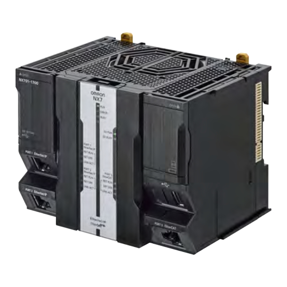
Models and Specifications Memory capacity for vari- Number of Database con- Model Program capacity ables motion axes nection NX701-1700 80 MB 4 MB (Retained during 256 axes Not supported. power interruptions) or 256 NX701-1600 128 axes MB (Not retained during... - Page 73 3 Configuration Units Letter Name Function Peripheral USB port Connects to the Sysmac Studio via a USB cable. DIP switch Used in Safe Mode or when backing up data . Normally, turn OFF all of the pins. Push switch Unused. For future expansion, leave it unoperated. Power supply connector Connects to the Power Supply Unit.
- Page 74 3 Configuration Units Operation Status Indicators There are the indicators to show the operation status of Unit in the center of the front side of the CPU Unit. ERROR BUSY Indicators at the top SD PWR SD BUSY PORT1 EtherNet/IP NET RUN NET ERR LINK/ACT...
- Page 75 3 Configuration Units The following table describes these indicators. Indicator Color Status Meaning Green Lit. The CPU Unit is in normal operation in RUN mode. (The user program is in execution.) Flashing The CPU Unit is starting (entering RUN mode or PROGRAM at 2-s mode at startup).
- Page 76 3 Configuration Units Precautions for Safe Use • Do not turn OFF the power supply to the Controller while the BUSY indicator flashes. While the BUSY indicator is lit, the user program and settings in the CPU Unit are being backed up in the built-in non-volatile memory.
- Page 77 3 Configuration Units Indicator Color Status Meaning NET ERR Not lit. There are no Ethernet communications errors. • The power supply is OFF or the CPU Unit was reset. Flashing An error for which the user can recover operation occurred. •...
- Page 78 3 Configuration Units Battery The following Battery is built in as a standard feature. Model Appearance Specification CJ1W-BAT01 Service life: 5 years For the battery lifetime, refer to Battery Service Life and Replacement Period on page 6-6. The following values are retained during power interruptions.
- Page 79 Shows the lot number and the serial number of the CPU Unit. number DDMYY: Lot number, : For use by OMRON, xxxx: Serial number M is 1 to 9 for January to September, X for October, Y for November, and Z for December.
-
Page 80: Sd Memory Cards
This section describes the models, specifications, and application of the SD Memory Cards. 3-2-1 Models and Specifications SD cards and SDHC cards are supported, but use one of the following OMRON Cards. OMRON is not responsible for the operation, performance, or write life of any other SD or SDHC card. Capacity... -
Page 81: Power Supply Units
3 Configuration Units Power Supply Units This section describes the models and specifications of the Power Supply Units as well as the names and functions of the parts. 3-3-1 Models and Specifications NX7-series Power Supply Units Use an NX7-series Power Supply Unit to supply power to an NX7-series CPU Unit. Item Specification Model... -
Page 82: Part Names And Functions
3 Configuration Units *5. Apply the voltage between the Power Supply Unit’s L1 or L2 terminal and the GR terminal when testing insulation and dielectric strength. The tests can also be performed with the LG terminal and GR terminal connected to each other. In this case, the leakage current will be 10 mA or less. - Page 83 3 Configuration Units • Back View Common in NX-PA9001/PD7001 Letter Name Function Dropout prevention lock release Releases the dropout prevention lock. lever DIN Track mounting hooks These hooks are used to mount the Unit to a DIN Track. Sliders Holds the Units together. PWR indicator Indicates that the power supply is operating.
- Page 84 3 Configuration Units Terminal Block Function Terminal Appear Name number ance NX-PA9001 NX-PD7001 Power sup- Supply 100 to 240 VAC. Supply 24 VDC. ply input Ground to a resistance of 100 Ω or less to increase noise resistance and avoid electric shock.
-
Page 85: Sysmac Studio
3 Configuration Units Sysmac Studio The Sysmac Studio is a Support Software package that provides an integrated development environ- ment to design, program, debug, and maintain SYSMAC NJ/NX-series Controllers. This section describes the models and connecting methods of the Sysmac Studio. 3-4-1 Model Numbers The model numbers of the Sysmac Studio Standard Edition are given in the following table. - Page 86 3 Configuration Units Connection with EtherNet/IP • 1:1 Connection • 1:N Connection Sysmac Studio Sysmac Studio EtherNet/IP EtherNet/IP • A direct connection is made from the Directly specify the IP address of the remote device. Sysmac Studio. The IP address and connection device do not need to be specified.
-
Page 87: Installation And Wiring
Installation and Wiring This section describes how to install and wire the NX-series NX701 CPU Unit as well as details on installation locations. 4-1 Processing at Power ON and Power OFF ......4-2 4-1-1 Power ON Operation . -
Page 88: Processing At Power On And Power Off
4 Installation and Wiring Processing at Power ON and Power WARNING • Do not touch the terminal section while power is ON. Electrical shock may occur. • Do not disassemble any of the Units. Particularly the Power Supply Units contain parts with high voltages when power is ON or immediately after power is turned OFF. -
Page 89: Power Off Operation
4 Installation and Wiring The following processing is performed during the startup status. Process Description Self diagnosis at startup Operation is monitored for the following errors: Power Supply Error, CPU Unit Reset, CPU Unit Watchdog Timer Error. Data check The _RetainFail (Retention Failure Flag) system-defined variable changes to TRUE at the following time: when the values of vari- ables for which the Retain attribute was set to retain the values and the values in DM, EM, and HR Areas in the memory used for... - Page 90 4 Installation and Wiring Power Supply Unit Power supply input Power interruption voltage model NX-PA9001 100 to 200 VAC 85 VAC max. NX-PD7001 24 VDC 20.4 VDC max. The setting ranges for the power OFF detection time are given in the following table. Power supply Power OFF detection time type...
-
Page 91: Resetting The Controller From The Sysmac Studio
4 Installation and Wiring Momentary Power Interruption with Continued Operation Execution of the user program will continue if a momentary power interruption is less than the following times. Power supply Momentary power interruption time type with continued operation AC power supply 30.5 ms max. -
Page 92: Fail-Safe Circuits
4 Installation and Wiring Fail-safe Circuits WARNING Provide safety measures in external circuits to ensure safety in the system if an abnormality occurs due to malfunction of the CPU Unit, other Units, or slaves or due to other external factors affecting operation. -
Page 93: Order Of Powering Up The Controller And Controlled System
4 Installation and Wiring 4-2-1 Order of Powering Up the Controller and Controlled System Outputs from Units, such as DC Output Units, may malfunction momentarily when the power to the Controller is turned ON. This may cause problems in the system if the Controller power supply is turned ON after the controlled system’s power supply. - Page 94 4 Installation and Wiring Interlock Circuits When the Controller controls an operation such as the clockwise and counterclockwise operation of a motor, provide an external interlock such as the one shown in the following example to prevent both the forward and reverse outputs from turning ON at the same time if required by the application. Example: Interlock circuit ON_MC1...
-
Page 95: Mounting Units
4 Installation and Wiring Mounting Units This section describes how to mount Units to the NX-series Controller. In this description, the combination of the NX-series CPU Unit and the NX-series Power Supply Unit is called a CPU Module. Precautions for Safe Use •... -
Page 96: Installation In A Control Panel
4 Installation and Wiring 4-3-1 Installation in a Control Panel Installation in Cabinets or Control Panels When the NX-series Controller is being installed in a cabinet or control panel, be sure to provide proper ambient conditions as well as access for operation and maintenance. ... - Page 97 4 Installation and Wiring Controller Orientation • Each Rack must be mounted in an upright position to provide proper cooling. • Do not install a Rack in any of the following positions. Mounting with the DIN Track on the Bottom Mounting with the DIN Track on the Top DIN Track DIN Track...
- Page 98 4 Installation and Wiring Additional Information A Controller must be mounted on DIN Track. It cannot be mounted with screws. Wiring Ducts Whenever possible, route I/O wiring through wiring ducts. Install mounting bracket so that it is easy to fish wire from the I/O Units through the duct. It is handy to have the duct at the same height as the CPU Rack.
- Page 99 4 Installation and Wiring Precautions for Correct Use Tighten terminal block screws and cable screws to the following torques. Terminal Screws M4: 1.2 N·m M3: 0.5 N·m Cable Connector Screws M2.6: 0.2 N·m Routing Wiring Ducts Install the wiring ducts at least 20 mm away from the tops of the Rack and any other objects (e.g., ceiling, wiring ducts, structural supports, devices, etc.) to provide enough space for air circulation and replacement of Units.
-
Page 100: Preparations For Installation
We recommend using the following products to install the Unit on a DIN Track. Name Model Manufacturer Remarks 35-mm DIN Track PFP-50N OMRON Corporation • Length: 50 cm • Material: Aluminum • Surface treatment: Insulated PFP-100N OMRON Corporation • Length: 100 cm •... - Page 101 4 Installation and Wiring DIN Tracks PFP-100N/50N DIN Track ± 0.15 ± ± 0.15 15 (5) 1,000 (500) *1. PFP-50N dimensions are given in parentheses. NS 35/ 7,5 PERF R0.8 R0.8 NS 35/ 15 PERF ° R1.25 R1.25 End Plate PFP-M (Two) CLIPFIX 35 (Two) NX-series CPU Unit Hardware User’s Manual (W535)
-
Page 102: Installing The Cpu Module
4 Installation and Wiring 4-3-3 Installing the CPU Module This section describes how to install the CPU Module. Precautions for Safe Use • Do not apply labels or tape to the Unit. When the Unit is installed or removed, adhesive or scraps may adhere to the pins in the NX bus connector, which may result in malfunctions. - Page 103 4 Installation and Wiring Install the DIN Track. • Using a PFP-50N/100N DIN Track Use one M4 screw for each three holes in the DIN Track. There must be a screw for each inter- val of 105 mm or less. The screw tightening torque is 1.2 N·m. DIN Track Use one screw for each three holes.
- Page 104 4 Installation and Wiring Make sure that the DIN Track mounting hooks on each Unit of the CPU Module are in the unlocked position. DIN Track mounting hooks 9.5 mm 4.5 mm DIN Track Mounting DIN Track Mounting Hooks in Locked Position Hooks in Unlocked Position If the DIN Track mounting hooks are pulled up, they are in the unlocked position.
- Page 105 4 Installation and Wiring (2) Press the DIN Track mounting hooks down to the locked position. After mounting, check to be sure that the CPU Module and the End Cover securely mounted on the DIN Track. NX-series CPU Unit Hardware User’s Manual (W535) 4 - 19...
-
Page 106: Mounting The End Cover
4 Installation and Wiring 4-3-4 Mounting the End Cover Use the following procedure to mount the End Cover if you removed it when mounting the Unit or if it is displaced from the CPU Unit. Precautions for Correct Use Always mount an End Cover to the end of the CPU Rack to protect the last Unit on the CPU Rack. -
Page 107: Mounting The End Plates
After you mount the Unit on the DIN Track, always secure it with End Plates at both sides. If you do not secure it, the Unit may be damaged or malfunction. Using PFP-M (OMRON) To mount an End Plate, 1) hook the bottom of it on the bottom of the DIN Track and 2) rotate the End Plate to hook the top of it on the top of the DIN Track. - Page 108 4 Installation and Wiring To remove an End Plate 1) insert the tip of a flat-blade screwdriver into groove “a” and 2) use “b” as a fulcrum and lift the end of the screwdriver, as shown in the following diagram. Flat-blade screwdriver 4 - 22 NX-series CPU Unit Hardware User’s Manual (W535)
-
Page 109: Installing And Removing The Sd Memory Card
• The service life may be extremely short if a non-OMRON SD Memory Card is used. Also, operation may be affected due to deterioration in writing performance. • If you use an OMRON SD Memory Card, the end of the life of the SD Memory Card can be detected in the following ways. - Page 110 4 Installation and Wiring Insert the SD Memory Card with the label facing to the right. Insert the SD Memory Card with the label facing the right side of the CPU Unit. Model number label Push the SD Memory Card securely into the compartment. 4 - 24 NX-series CPU Unit Hardware User’s Manual (W535)
- Page 111 4 Installation and Wiring Removing the SD Memory Card Press the SD Memory Card power supply switch. S D P W R SD Memory Card power supply switch Press the SD Memory Card after the SD BUSY indicator is no longer lit. SD Memory Card The SD Memory Card will be ejected from the compartment.
- Page 112 4 Installation and Wiring Close the CPU Unit cover when an SD Memory Card is not being used. 4 - 26 NX-series CPU Unit Hardware User’s Manual (W535)
-
Page 113: Removing The Cpu Module
4 Installation and Wiring 4-3-7 Removing the CPU Module This section describes how to remove the CPU Module. Precautions for Safe Use • Do not apply labels or tape to the Unit. When the Unit is installed or removed, adhesive or scraps may adhere to the pins in the NX bus connector, which may result in malfunctions. - Page 114 4 Installation and Wiring Unlock the DIN Track mounting hook. Use a flat-blade screwdriver to pull up the DIN Track mounting hook on the CPU Module to unlocked position. At this point, be sure not to drop the CPU Module. Remove the CPU Module from the DIN Track.
-
Page 115: Assembled Appearance And Dimensions
4 Installation and Wiring 4-3-8 Assembled Appearance and Dimensions Installation Dimensions End Cover Power Supply Unit End Plate 1.35 CPU Unit End Plate DIN Track 32.5 104.5 32.5 94.2 W+(C)+(C) Unit: [mm] Unit: [mm] W: Total width of the Power Supply Unit and CPU Unit (the End Cover is included in the CPU Unit width) •... - Page 116 4 Installation and Wiring Installation Height With a height of 100 mm, the CPU Unit is the highest component in an NX-series CPU Rack. When a cable is connected (such as a Unit communications cable), however, even greater height is required. Allow sufficient depth in the control panel containing the Controller.
-
Page 117: Wiring
4 Installation and Wiring Wiring WARNING • Do not input a voltage or current that exceeds the specified range into a Unit or slave. If a volt- age or current that is outside the specified range is input, the Unit or slave may fail or a fire may occur. - Page 118 4 Installation and Wiring AC Power Supply • Supply 100 to 240 VAC. • Use the Power Supply Unit of the voltage and frequency shown in the table below. Model Power supply voltage NX-PA9001 100 to 240 VAC 50/60 Hz (85 to 264 VAC, 47 to 63 Hz) •...
- Page 119 4 Installation and Wiring DC Power Supplies Precautions When Using A Non-isolated Power Supply Unit NX-PD7001 CAUTION When you connect a computer or other peripheral device to a Controller that has a non-isolated DC Power Supply Unit NX-PD7001, either ground the 0-V side of the external power supply or do not ground it at all.
- Page 120 ON. Refer to 3-3-1 Models and Specifications on page 3-11 for inrush current specifications. We recommend that you use the OMRON S8JX-series or S8VS-series Power Supplies, all of which have the capacity of 180 W or greater.
-
Page 121: Grounding
4 Installation and Wiring 4-4-2 Grounding This section describes how to ground the CPU Rack. Units with Ground Terminals and Type of Ground Terminals Power Supply Units Power Supply Units NX-PA9001 and NX-PD7001 PA9001 LG (Noise-filter neutral terminal) Ground this terminal to less than 100 Ω AC100-2 INPUT to improve noise resistance and prevent... - Page 122 4 Installation and Wiring DIN Track Contact Plates A Unit that has a ground terminal also has a DIN Track contact plate on the back of the Unit. The DIN Track contact plate is connected internally to the ground terminal on the Unit. This means that the ground terminal will be electrically connected to the DIN Track.
- Page 123 If the ground wire for a Unit with a ground terminal is shared with power equipment, noise will adversely affect the Units. You can use OMRON NX-AUX01 DIN Track Insulation Spacers with PFP-50N or PFP-100N DIN Tracks to isolate the CPU Rack from the control panel.
-
Page 124: Wiring The Built-In Ethercat Port
4 Installation and Wiring • DIN Track Insulation Spacers NX-AUX01 (OMRON Corporation) Three Spacers are included in one model. 14.8 Precautions for Correct Use If you use DIN Track Insulation Spacers to install a CPU Rack, the height will be increased by approximately 10 mm. -
Page 125: Control Panel Installation
4 Installation and Wiring Control Panel Installation To ensure system reliability and safety, the system must be designed and configured according to the installation environment (temperature, humidity, vibration, shock, corrosive gases, overcurrent, noise, etc.). 4-5-1 Temperature Panels have been reduced in size due to space-saving and miniaturization in devices and systems, and the temperature inside the panel may be at least 10 to 15°C higher than outside the panel. - Page 126 4 Installation and Wiring Forced Ventilation (by Fan at Top of Panel) Controller Controller Air filter Forced Ventilation Method Forced Air Circulation (by Fan in Closed Panel) Controller Controller Forced Air Circulation Room Cooling (Cooling the Entire Room Where the Control Panel Is Located) Cooler Control panel Room Cooling...
-
Page 127: Humidity
4 Installation and Wiring 4-5-2 Humidity Rapid temperature changes can cause condensation to occur, resulting in malfunctioning due to short-circuiting. When there is a possibility of this occurring, take measures against condensation, such as leaving the Controller power ON at night or installing a heater in the control panel to keep it warmer. Control panel Moisture absorber... -
Page 128: Electrical Environment
4 Installation and Wiring 4-5-5 Electrical Environment When installing or wiring devices, make sure that there will be no danger to people and that noise will not interfere with electrical signals. Controller Installation Location Install the Controller as far away as possible from high-voltage (600 V or higher) and power devices to ensure safe operation and maintenance. - Page 129 4 Installation and Wiring Wire Layout for the Power Supply System Observe the following points when wiring the power supply system. • Separate the Controller power supply from the I/O device power supply and install a noise filter near the Controller power supply feed section. •...
- Page 130 4 Installation and Wiring • Never bundle output signal lines with high-voltage or power lines, and do not route them in close proximity or parallel to such lines. If output signal lines must be routed in close proximity to such lines, place them in separate ducts or conduits.
- Page 131 4 Installation and Wiring Wiring Observe the following points when wiring power supply and signal cables. • When routing signal cables with differing characteristics through the same duct, always keep them separated. • As much as possible, avoid routing multiple power supply lines through the same duct. If it cannot be avoided, then construct a partition between them in the duct and ground the parti- tion.
-
Page 132: Grounding
4 Installation and Wiring • Either install the Controller a minimum of 200 mm away from high-voltage lines or power lines, or place the high-voltage lines or power lines in metal tubing and completely ground the metal tubing to 100 Ω or less. High-voltage power panel Metal tubing Power lines... - Page 133 4 Installation and Wiring Additional Information • In a country or region where the earthing method is regulated, you must comply with the reg- ulations. Refer to the applicable local and national ordinances of the place where you install the system, or other international laws and regulations. •...
- Page 134 4 Installation and Wiring a) Connecting devices and noise sources to separate earth electrodes This is an earthing method to separately ground an earth electrode of the device that is con- nected with a communications cable or other devices and an earth electrode of a high-power device that could be a noise source, such as a motor or inverter.
- Page 135 4 Installation and Wiring Control panel A device that could be Other device NX-series CPU Units NX-AUX01 a noise source Precautions for Grounding General Precautions • To prevent electrical shock, do not connect devices to ground poles (or steel frames) with non-equalized potential to which multiple devices are connected.
- Page 136 4 Installation and Wiring Controller Ground Terminals The Controller has the following two ground terminals. Terminal Grounding Symbol Connection name type Functional Ground this terminal when power supply noise causes malfunc- Grounding tioning. Protective Always ground this terminal to prevent electrical shock. Grounding When the functional ground terminal is correctly grounded, it is generally effective in suppressing power supply common noise.
-
Page 137: Troubleshooting
Troubleshooting This section describes the confirmation methods and corrections for errors that occur in the NX-series NX701 Controller and describes hardware-related errors that can occur in the PLC Function Module. 5-1 Operation after an Error ........5-2 5-1-1 Overview of NX-series Status . -
Page 138: Operation After An Error
5 Troubleshooting Operation after an Error This section describes the error status of the NX-series Controller and the operation that occurs after an error is detected. Refer to 5-2 Troubleshooting for details on corrections for specific errors. Refer to the NJ/NX-series Troubleshooting Manual (Cat. No. W503) for all of the errors that may occur in an NX- series Controller. -
Page 139: Fatal Errors In The Cpu Unit
5 Troubleshooting *1 Refer to 5-1-2 Fatal Errors in the CPU Unit for information on individual errors. *2 Refer to 5-1-3 Non-fatal Errors in the CPU Unit for information on individual errors. *3 The function module where the error occurred stops. 5-1-2 Fatal Errors in the CPU Unit Types of Fatal Errors... -
Page 140: Non-Fatal Errors In The Cpu Unit
5 Troubleshooting 5-1-3 Non-fatal Errors in the CPU Unit Event Levels Non-fatal errors that occur are managed as Controller events in the NX-series Controller. Controller events are classified into levels according to the degree of the effect that the events have on control. When an event occurs, the Sysmac Studio or HMI will display the level. - Page 141 5 Troubleshooting Operation for Each Level The operation that is performed when an error occurs depends on the error level of the Controller event. Event level Controller infor- Item Controller errors mation Major fault level Partial fault level Minor fault level Observation Information These errors are...
- Page 142 5 Troubleshooting Event level Controller infor- Item Controller errors mation Major fault level Partial fault level Minor fault level Observation Information RUN out- put on Power Supply Unit User pro- Stops. Continues. Continues. Continues. Continues. gram exe- Operation cution of NX- status series CPU Outputs...
- Page 143 5 Troubleshooting Operation in the Function Module Where an Error Event Occurred Event level Function module Major fault level Partial fault level Minor fault level Observation PLC Function User program execu- Operation continues. Module tion stops. All axes stop. (The stop •...
- Page 144 5 Troubleshooting Checking for Non-fatal Errors Use the following methods to check for non-fatal errors. Checking method What you can check Checking the indicators You can use the indicators to confirm the Controller error level, the error status of the EtherCAT Master Function Module, and the error status of the Ether- Net/IP Function Module.
- Page 145 • Lit: An error for which normal status cannot be recovered through user actions (i.e., errors for which you must replace the CPU Unit or contact your OMRON representative) has occurred. • Flashing: An error for which normal status can be recovered through user actions has occurred.
- Page 146 5 Troubleshooting Checking with the Troubleshooter of an HMI If you can connect communications between an HMI and the Controller when an error occurs, you can check for current Controller errors and the log of past Controller errors. To perform troubleshooting from an HMI, connect the HMI to the built-in EtherNet/IP port on the CPU Unit.
-
Page 147: Troubleshooting
5 Troubleshooting Troubleshooting This section provides basic error identification and troubleshooting flowcharts. Use them when an error occurs in the NX-series Controller. This section also describes the hardware errors that are related to the PLC Function Module and corrections for those errors. 5-2-1 Checking to See If the CPU Unit Is Operating When an error occurs in the NX-series Controller, use the following flowchart to determine whether the... -
Page 148: Troubleshooting Flowchart For Non-Fatal Errors
5 Troubleshooting 5-2-2 Troubleshooting Flowchart for Non-fatal Errors For a non-fatal error, use the Sysmac Studio or an HMI to troubleshoot the error with the following flow- chart. You can use the indicators to check the following: • Level • Whether the error is in the EtherNet/IP port or the EtherCAT port •... -
Page 149: Error Table
5 Troubleshooting 5-2-3 Error Table The hardware errors (i.e., events) and the Controller operation errors (i.e., events) that involve hard- ware that can occur in the PLC Function Module are given on the following pages. The following abbre- viations and symbols are used in the event level column. Abbreviation Name Major fault level... - Page 150 5 Troubleshooting Level Event code Event name Meaning Assumed cause Reference Obs Info 10010000 hex Non-volatile An error was • The Controller power supply page 5-33 Memory detected in the non- was turned OFF while the Restored or volatile memory BUSY indicator was lit.
- Page 151 5 Troubleshooting Level Event code Event name Meaning Assumed cause Reference Obs Info 00070000 hex Real-Time The oscillation of • The battery voltage is low. page 5-40 Clock the real-time clock • The battery connector has Stopped stopped. The real- come loose.
- Page 152 5 Troubleshooting Level Event code Event name Meaning Assumed cause Reference Obs Info 10060000 hex SD Memory A file that must be • The Controller power supply page 5-46 Card Data in the SD Memory was turned OFF while the SD Corrupted Card is missing or BUSY indicator was lit.
- Page 153 5 Troubleshooting Errors Related to Controller Operation Level Event code Event name Meaning Assumed cause Reference Obs Info 10200000 hex User Pro- The user program • The user program or Controller page 5-48 gram/Con- or Controller Con- Configurations and Setup are troller figurations and not correct because the power...
- Page 154 5 Troubleshooting Level Event code Event name Meaning Assumed cause Reference Obs Info 10270000 hex Error in Start- An error was • An SD Memory Card is not page 5-51 ing Automatic detected in pre- inserted. Transfer execution checks • The SD Memory Card type is for automatic trans- not correct.
- Page 155 5 Troubleshooting Level Event code Event name Meaning Assumed cause Reference Obs Info 10280000 hex Error in Exe- The automatic • It was not possible to read the page 5-53 cuting Auto- transfer ended in an data for automatic transfer. matic error.
- Page 156 5 Troubleshooting Level Event code Event name Meaning Assumed cause Reference Obs Info 10330000 hex SD Memory An error was • An SD Memory Card is not page 5-54 (Ver. 1.11 or Card Pro- detected in pre- inserted. later) gram Trans- execution checks •...
- Page 157 5 Troubleshooting Level Event code Event name Meaning Assumed cause Reference Obs Info 10340000 hex Error in Exe- The SD Memory • It was not possible to read the page 5-57 (Ver. 1.11 or cuting SD Card program data for SD Memory Card pro- later) Memory Card transfer ended in an...
- Page 158 5 Troubleshooting Level Event code Event name Meaning Assumed cause Reference Obs Info 10290000 hex Backup An error was • An SD Memory Card is not page 5-61 Failed to detected in pre- inserted. Start execution checks • The SD Memory Card type is for a backup opera- not correct.
- Page 159 5 Troubleshooting Level Event code Event name Meaning Assumed cause Reference Obs Info 102B0000 hex Restore An error was • An SD Memory Card is not page 5-64 Operation detected in pre- inserted. Failed to execution checks • The SD Memory Card type is Start for a restore opera- not correct.
- Page 160 5 Troubleshooting Level Event code Event name Meaning Assumed cause Reference Obs Info • Password of Restore by sys- tem-defined variable in the Controller Setup does not agree with the _Card1Resto- reCmd.Password system- defined variable. • The DIP switch on the CPU Unit is not set to allow starting the restore of SD Memory Card backups by specification with...
- Page 161 5 Troubleshooting Level Event code Event name Meaning Assumed cause Reference Obs Info 10320000 hex SD Memory An error was • Program transfer by system- page 5-68 defined variable is set to Do not (Ver. 1.11 or Card Pro- detected in pre-start use in the Controller Setup.
- Page 162 5 Troubleshooting Level Event code Event name Meaning Assumed cause Reference Obs Info • The robot version of the CPU Unit to which to transfer the files is older than the robot ver- sion of the backup files on the SD Memory Card.
- Page 163 5 Troubleshooting Level Event code Event name Meaning Assumed cause Reference Obs Info 40140000 hex PLC System This event pro- • This event provides internal page 5-73 Information vides internal infor- information from the PLC Func- mation from the tion Module. It is recorded to PLC Function Mod- provide additional information ule.
- Page 164 5 Troubleshooting Level Event code Event name Meaning Assumed cause Reference Obs Info 90120000 hex Power Inter- The power supply • The power supply was inter- page 5-79 rupted was interrupted. rupted. 90130000 hex Operation Operation was • A command to start operation page 5-79 Started started.
-
Page 165: Error Descriptions
5 Troubleshooting 5-2-4 Error Descriptions This section describes the information that is given for individual errors. Controller Error Descriptions The items that are used to describe individual errors (events) are described in the following copy of an error table. Event name Gives the name of the error. - Page 166 5 Troubleshooting Errors for Self Diagnosis Event name DIP Switch Setting Error Event code 00090000 hex Meaning An error was detected in the DIP switch setting. Source PLC Function Module Source details None Detection At power ON or timing Controller reset Error attributes Level Major fault...
- Page 167 5 Troubleshooting Event name Non-volatile Memory Life Exceeded Event code 000E0000 hex Meaning The specified number of deletions for non-volatile memory was exceeded. Or, the number of bad blocks in memory exceeded the specified value. Source PLC Function Module Source details None Detection Continuously...
- Page 168 5 Troubleshooting Event name Main Memory Check Error Event code 00130000 hex Meaning An error was detected in the memory check of the main memory in the CPU Unit. Source PLC Function Module Source details None Detection Continuously timing Error attributes Level Major fault Recovery...
- Page 169 5 Troubleshooting Event name Non-volatile Memory Restored or Formatted Event code 10010000 hex Meaning An error was detected in the non-volatile memory check and file system recovery or formatting was executed. Previous files may have been deleted. Source PLC Function Module Source details None Detection...
- Page 170 5 Troubleshooting Event name Non-volatile Memory Data Corrupted Event code 10020000 hex Meaning A file that must be in non-volatile memory is missing or corrupted. Source PLC Function Module Source details None Detection At power ON or timing Controller reset Error attributes Level Major fault...
- Page 171 5 Troubleshooting Event name Main Memory Check Error Event code 10080000 hex Meaning An error was detected in the memory check of the main memory in the CPU Unit. Source PLC Function Module Source details None Detection Continuously timing Error attributes Level Major fault Recovery...
- Page 172 5 Troubleshooting Event name Data Not Saved to Battery-backup Memory Event code 100A0000 hex Meaning An error occurred in the software and data could not be saved in battery-backup memory during power-OFF process- ing. Source PLC Function Module Source details None Detection At power ON or...
- Page 173 5 Troubleshooting Event name Non-volatile Memory Data Corrupted Event code 100B0000 hex Meaning A file that must be in non-volatile memory is missing or corrupted. Source PLC Function Module Source details None Detection At power ON or timing Controller reset Error attributes Level Major fault...
- Page 174 5 Troubleshooting Event name Event Level Setting Error Event code 100C0000 hex Meaning The settings in the event level setting file are not correct. Source PLC Function Module Source details None Detection At power ON or timing Controller reset Error attributes Level Major fault Recovery...
- Page 175 None Cause and Assumed cause Correction Prevention correction An error occurred in the software. Contact your OMRON representative. None Attached None information Precautions/ None Remarks * For details, refer to I/O Operation for Major Fault Level Controller Errors on page 5-7.
- Page 176 None Cause and Assumed cause Correction Prevention correction An error occurred in the software. Contact your OMRON representative. None Attached None information Precautions/ None Remarks * For details, refer to I/O Operation for Major Fault Level Controller Errors on page 5-7.
- Page 177 5 Troubleshooting Event name Real-Time Clock Failed Event code 00080000 hex Meaning The real-time clock in the CPU Unit failed. Source PLC Function Module Source details None Detection At power ON or timing Controller reset Error attributes Level Minor fault Recovery Cycle the power Log category...
- Page 178 5 Troubleshooting Event name CPU Unit Overheat Event code 000C0000 hex Meaning The temperature inside the CPU Unit exceeded the specified value. Source PLC Function Module Source details None Detection Continuously timing Error attributes Level Minor fault Recovery Cycle the power Log category System supply or reset...
- Page 179 5 Troubleshooting Event name Battery-backup Memory Check Error Event code 10090000 hex Meaning An error was detected in the memory check of the battery-backup memory in the CPU Unit. Source PLC Function Module or Motion Con- Source details PLC Function Detection At power ON or trol Function Module...
- Page 180 The file format of the SD Memory Make sure that the correct SD Mem- Use an OMRON SD Memory Card. Card inserted in the CPU Unit is not ory Card is inserted in the CPU Unit. Do not format the SD Memory Card FAT16 or FAT32.
- Page 181 5 Troubleshooting Event name SD Memory Card Restored or Formatted Event code 10040000 hex Meaning An error was detected during the file system check and the file system was restored. Files may have been deleted. Source PLC Function Module Source details None Detection At power ON or...
- Page 182 5 Troubleshooting Event name SD Memory Card Data Corrupted Event code 10060000 hex Meaning A file that must be in the SD Memory Card is missing or corrupted. Source PLC Function Module Source details None Detection At power ON or timing Controller reset Error attributes...
- Page 183 5 Troubleshooting Event name SD Memory Card Access Power OFF Error Event code 10070000 hex Meaning The power supply to the Controller was interrupted during access to the SD Memory Card. Source PLC Function Module Source details None Detection At power ON or timing Controller reset Error attributes...
- Page 184 5 Troubleshooting Errors Related to Controller Operation Event name User Program/Controller Configurations and Setup Trans- Event code 10200000 hex fer Error Meaning The user program or Controller Configurations and Setup were not transferred correctly. Source PLC Function Module Source details None or I/O bus Detection At power ON or...
- Page 185 5 Troubleshooting Event name Illegal User Program Execution ID Event code 10210000 hex Meaning The user program execution IDs set in the user program and in the CPU Unit do not match. Source PLC Function Module Source details None Detection At user program timing download, power...
- Page 186 5 Troubleshooting Event name Illegal User Program/Controller Configurations and Setup Event code 10250000 hex Meaning The upper limit of the usable memory was exceeded or the user program or Controller Configurations and Setup is cor- rupted. Source PLC Function Module Source details None Detection...
- Page 187 5 Troubleshooting Event name Error in Starting Automatic Transfer Event code 10270000 hex Meaning An error was detected in pre-execution checks for automatic transfer. Source PLC Function Module Source details None Detection At power ON timing Error attributes Level Major fault Recovery Cycle the power Log category...
- Page 188 5 Troubleshooting Cause and The model of the CPU Unit to which Replace the CPU Unit with a CPU Make sure that the model of the CPU correction to transfer the files is not the same as Unit that has the same model as the Unit is the same as the model of the the model of the CPU Unit of the CPU Unit that was used to create the...
- Page 189 5 Troubleshooting Event name Error in Executing Automatic Transfer Event code 10280000 hex Meaning The automatic transfer ended in an error. Source PLC Function Module Source details None Detection At power ON timing Error attributes Level Major fault Recovery Cycle the power Log category System supply or reset...
- Page 190 5 Troubleshooting Event name SD Memory Card Program Transfer Pre-execution Check Event code 10330000 hex Error Meaning An error was detected in pre-execution checks for transferring SD Memory Card programs. Source PLC Function Module Source details None Detection Before SD Mem- timing ory Card pro- grams are...
- Page 191 5 Troubleshooting Cause and Assumed cause Correction Prevention correction The model of the CPU Unit to which Replace the CPU Unit with a CPU Make sure that the model of the CPU to transfer the files is not the same as Unit that has the same model as the Unit is the same as the model of the the model of the CPU Unit of the...
- Page 192 5 Troubleshooting Attached Attached Information 1: Error Details information 0001 hex: An SD Memory Card is not inserted. 0002 hex: The SD Memory Card is faulty, the format of the SD Memory Card is not correct, or the SD Memory Card is not the correct type of card.
- Page 193 5 Troubleshooting Event name Error in Executing SD Memory Card Program Transfer Event code 10340000 hex Meaning The SD Memory Card program transfer ended in an error. Source PLC Function Module Source details None Detection During SD Mem- timing ory Card program transfers Error attributes Level...
- Page 194 None Cause and Assumed cause Correction Prevention correction An error occurred in the software. Contact your OMRON representative. None Attached Attached information 1: System information information Attached Information 2: System information Attached information 3: System information Attached information 4: System information...
- Page 195 None Cause and Assumed cause Correction Prevention correction An error occurred in the software. Contact your OMRON representative. None Attached Attached information 1: System information information Attached Information 2: System information Attached information 3: System information Attached information 4: System information...
- Page 196 5 Troubleshooting Event name Event Log Save Error Event code 10230000 hex Meaning Saving the event log failed. Source PLC Function Module Source details None Detection At power ON or timing Controller reset Error attributes Level Observation Recovery Log category System Effects User program...
- Page 197 5 Troubleshooting Event name Backup Failed to Start Event code 10290000 hex Meaning An error was detected in pre-execution checks for a backup operation. Source PLC Function Module Source details None Detection When backup is timing specified by the user Error attributes Level Observation...
- Page 198 5 Troubleshooting Cause and The SD Memory Card is damaged. If none of the above causes applies, Do not remove the SD Memory Card correction replace the SD Memory Card. or turn OFF the power supply while the SD BUSY indicator is lit. Replace the SD Memory Card periodically according to the write life of the SD Memory Card.
- Page 199 5 Troubleshooting Event name Backup Failed Event code 102A0000 hex Meaning The backup operation ended in an error. Source PLC Function Module Source details None Detection During backup timing operation Error attributes Level Observation Recovery Log category System Effects User program Continues.
- Page 200 5 Troubleshooting Event name Restore Operation Failed to Start Event code 102B0000 hex Meaning An error was detected in pre-execution checks for a restore operation. Source PLC Function Module Source details None Detection When restoring timing data is specified by the user Error attributes Level Observation...
- Page 201 5 Troubleshooting Cause and The SD Memory Card is damaged. If none of the above causes applies, Do not remove the SD Memory Card correction replace the SD Memory Card. or turn OFF the power supply while the SD BUSY indicator is lit. Replace the SD Memory Card periodically according to the write life of the SD Memory Card.
- Page 202 5 Troubleshooting Attached Attached information 1: Operation type information 0101 hex: SD Memory Card to Controller for switch operation on front of CPU Unit 0102 hex: SD Memory Card to Controller for specification with a system-defined variable 0201 hex: Computer to Controller Attached Information 2: Error Details 0001 hex: An SD Memory Card is not inserted.
- Page 203 5 Troubleshooting Event name Restore Operation Failed Event code 102C0000 hex Meaning The restore operation ended in an error. Source PLC Function Module Source details None Detection During restore timing operation Error attributes Level Observation Recovery Log category System Effects User program Operation Not affected.
- Page 204 5 Troubleshooting Event name SD Memory Card Program Transfer Failed to Start Event code 1032 0000 hex Meaning An error was detected in pre-start checks for transferring SD Memory Card programs. Source PLC Function Module Source details None Detection When transfer- timing ring SD Memory Card programs is...
- Page 205 5 Troubleshooting Cause and Assumed cause Correction Prevention correction The unit version of the CPU Unit to Replace the CPU Unit with a CPU Make sure that the unit version of the which to transfer the files is older than Unit that has a unit version that is the CPU Unit and the unit version of the the unit version of the backup files on...
- Page 206 5 Troubleshooting Attached Attached Information 1: Error Details information 0001 hex: An SD Memory Card is not inserted. 0002 hex: The SD Memory Card is faulty, the format of the SD Memory Card is not correct, or the SD Memory Card is not the correct type of card.
- Page 207 5 Troubleshooting Event name Restore Pre-execution Check Failure Event code 103E0000 hex Meaning An error was detected in pre-execution checks for specification with system-defined variables for the SD Memory Card restore operation. Source PLC Function Module Source details None Detection Before the timing restore operation...
- Page 208 5 Troubleshooting Cause and Assumed cause Correction Prevention correction The CPU Unit is write-protected. If you transfer SD Memory Card pro- If you transfer SD Memory Card pro- grams, select the Do not use Option grams, select the Do not use Option for the Write protection at startup set- for the Write protection at startup set- ting of the CPU Unit.
- Page 209 5 Troubleshooting Event name PLC System Information Event code 40140000 hex Meaning This event provides internal information from the PLC Function Module. Source PLC Function Module Source details None Detection Continuously timing Error attributes Level Observation Recovery Log category System Effects User program Continues.
- Page 210 5 Troubleshooting Event name NX Message Communications Error Event code 80230000 hex Meaning An error has occurred in message communications. Source PLC Function Module Source details None Detection During NX mes- timing sage communi- EtherCAT Master Function Module cations EtherNet/IP Function Module Error attributes Level Observation...
- Page 211 5 Troubleshooting Event name PLC System Information Event code 44430000 hex Meaning This event provides internal information from the PLC Function Module. Source PLC Function Module Source details None Detection Continuously timing Error attributes Level Information Recovery Log category System Effects User program Continues.
- Page 212 5 Troubleshooting Event name User Program/Controller Configurations and Setup Down- Event code 90050000 hex loaded Meaning The user program and the Controller configurations and setup were downloaded. Source PLC Function Module Source details None Detection During user pro- timing gram/Controller configurations and setup down- load...
- Page 213 5 Troubleshooting Event name Variable Changed to TRUE with Forced Refreshing Event code 90080000 hex Meaning Changing a variable to TRUE with forced refreshing was specified. Source PLC Function Module Source details None Detection Commands from timing user Error attributes Level Information Recovery...
- Page 214 5 Troubleshooting Event name Memory All Cleared Event code 900B0000 hex Meaning All of memory was cleared. Source PLC Function Module Source details None Detection Commands from timing user Error attributes Level Information Recovery Log category Access Effects User program Operation Operation returns to the factory state.
- Page 215 5 Troubleshooting Event name Power Turned ON Event code 90110000 hex Meaning The power supply was turned ON. Source PLC Function Module Source details None Detection At power ON timing Error attributes Level Information Recovery Log category System Effects User program ---- Operation Operation starts.
- Page 216 5 Troubleshooting Event name Operation Stopped Event code 90140000 hex Meaning Operation was stopped. Source PLC Function Module Source details None Detection When changing timing to PROGRAM mode Error attributes Level Information Recovery Log category System Effects User program Stops. Operation User program execution stops.
- Page 217 5 Troubleshooting Event name All Controller Errors Cleared Event code 90180000 hex Meaning All current errors were cleared. Source PLC Function Module Source details None Detection Commands from timing user Error attributes Level Information Recovery Log category Access Effects User program Continues.
- Page 218 5 Troubleshooting Event name Backup Completed Event code 901B0000 hex Meaning The backup operation ended normally. Source PLC Function Module Source details None Detection At end of normal timing backup operation Error attributes Level Information Recovery Log category System Effects User program Continues.
- Page 219 5 Troubleshooting Event name Restore Operation Completed Event code 901D0000 hex Meaning The restore operation ended normally. Source PLC Function Module Source details None Detection At end of normal timing restore operation Error attributes Level Information Recovery Log category System Effects User program Operation...
- Page 220 5 Troubleshooting Event name SD Memory Card Program Transfer Completed Event code 90210000 hex Meaning Transferring the SD Memory Card programs was completed. Source PLC Function Module Source details None Detection When transfer- timing ring SD Memory Card programs is completed Error attributes Level...
- Page 221 Inspection and Maintenance This section describes the required inspections and maintenance for the NX-series NX701 CPU Unit. It also describes the service lives and replacement procedures for the Battery and Power Supply Units. 6-1 Cleaning and Maintenance ........6-2 6-1-1 Cleaning .
-
Page 222: Cleaning And Maintenance
6 Inspection and Maintenance Cleaning and Maintenance This section describes daily maintenance and the cleaning and inspection methods. Inspect the NX-series CPU Unit daily or periodically in order to keep it in optimal operating condition. 6-1-1 Cleaning Perform the following cleaning procedures periodically to ensure the NX-series CPU Unit is maintained in the best operating condition. - Page 223 6 Inspection and Maintenance Periodic Inspection Items Inspec- Inspection details Criteria Correction tion item External Check for voltage fluctua- The voltage must be Use a voltage tester to check the power tions at the power supply ter- within the allowable power supply at the terminals.
- Page 224 6 Inspection and Maintenance Inspec- Inspection details Criteria Correction tion item User-ser- Battery Set Service life expectancy Replace the battery when its service viceable is 5 years at 25°C. life has passed even if a battery CJ1W-BAT01 parts error has not occurred. (Battery life Depending on model Check whether the battery depends upon the model, and ambi-...
-
Page 225: Unit Replacement Precautions
6 Inspection and Maintenance 6-1-3 Unit Replacement Precautions Check the following after replacing any faulty Unit. • Do not replace a Unit until the power is turned OFF. • Check the new Unit to make sure that there are no errors. •... -
Page 226: Replacing The Battery
6 Inspection and Maintenance Replacing the Battery The Battery in the NX-series CPU Unit must be replaced periodically as preventative maintenance. (The Battery is a backup power supply for the CPU Unit’s internal clock and the variables that are retained during power interruptions.) This section describes how to replace the Battery. 6-2-1 Battery Replacement Purpose of the Battery... - Page 227 6 Inspection and Maintenance Battery service life (minimum lifetime) [month] Power ON Unit model number time rate 25°C 40°C 55°C NX701- 100% Additional Information The Battery installed at the time of purchase is only for monitoring purpose to test the battery backup function.
- Page 228 6 Inspection and Maintenance Replacement Battery Use the Battery CJ1W-BAT01 for replacement. Precautions for Correct Use Be sure to install a replacement Battery within two years of the production date shown on the Battery label. Production Date CJ1W-BAT01 15-03 Manufactured in March 2015.
- Page 229 6 Inspection and Maintenance Replace the battery. (1) Pull the upper side of the right CPU Unit cover forward and remove from the Unit. (2) Draw out the battery from the battery connector and replace a new battery. When placing the new battery, hanging battery wires on the protrusion for placing wires will allow for compact storage of wires.
-
Page 230: Operation Without A Battery
6 Inspection and Maintenance Precautions for Safe Use • Before you replace the Battery, you must first supply power to the Controller for at least 5 minutes, and then you must complete this procedure within 5 minutes at 25°C after turning OFF the power to the CPU Unit to ensure memory backup. -
Page 231: Replacing The Fan Unit
6 Inspection and Maintenance Replacing the Fan Unit This section describes how to replace the Fan Unit, a part of the NX7-series CPU Unit that allows replacement as preventive maintenance. 6-3-1 Purpose of Attaching the Fan Unit A CPU that is incorporated in an NX7-series CPU Unit requires forced cooling to maintain its perfor- mance. -
Page 232: Procedure Of Fan Unit Replacement
6 Inspection and Maintenance Additional Information The date of manufacturing can be checked on the side of the Fan Unit. DDMYY gives the lot number, and “M” gives the following meaning. 1 to 9: January to September, X: October, Y: November, Z: December DDMYY 6-3-4 Procedure of Fan Unit Replacement... - Page 233 6 Inspection and Maintenance Attach the new Fan Unit. (1) Put the locating part of the Fan Unit to the locating part on the back of the CPU Unit. (2) Use the locating part as a supporting point and push the Fan Unit into the CPU Unit. Make sure that the lever is securely locked and there is no lifting-off of the Fan Unit.
- Page 234 6 Inspection and Maintenance 6 - 14 NX-series CPU Unit Hardware User’s Manual (W535)
-
Page 235: Appendices
Appendices The appendices provide the general specifications of the NX-series NX701 CPU Unit and Unit dimensions. A-1 Specifications ..........A-2 A-2 Dimensions . -
Page 236: A-1 Specifications
Shipbuilding Standards NK, LR standards Other than the above. *1. Refer to the OMRON website (http://www.ia.omron.com/) or consult your OMRON representative for the most recent applicable standards for each model. A - 2 NX-series CPU Unit Hardware User’s Manual (W535) -
Page 237: A-2 Dimensions
Appendices A-2 Dimensions Dimensions of the CPU Units are shown as follows. The unit of dimension is millimeter. A-2-1 NX-series CPU Units NX701- ERROR BUSY SHTDWN SD PWR SD BUSY PORT1 EtherNet/IP NET RUN NET ERR LINK/ACT PORT1 EtherNet/IP PORT2 PORT3 EtherNet/IP EtherCAT... -
Page 238: A-2-2 End Cover
Appendices A-2-2 End Cover A-2-3 NX-series Power Supply Units NX-PA9001 A - 4 NX-series CPU Unit Hardware User’s Manual (W535) -
Page 239: A-2-4 Sd Memory Card
Appendices NX-PD7001 A-2-4 SD Memory Card ± ± 0.15 ± NX-series CPU Unit Hardware User’s Manual (W535) A - 5... -
Page 240: A-3 Version Information
Appendices A-3 Version Information This section describes the relationship between the unit versions of the NX-series CPU Units and the Sysmac Studio versions, and the functions that are supported for each unit version. A-3-1 Relationship between Unit Versions of CPU Units and Sysmac Studio Versions This section also describes how the unit version of NX-series CPU Units correspond to Sysmac Studio versions. - Page 241 Appendices the Sysmac Studio. You can use only the functions that are supported by the unit version of the con- nected CPU Unit. Example: Unit version of CPU Unit: 1.10 Sysmac Studio version: 1.15 Unit version 1.11 of the CPU Unit corresponds to Sysmac Studio version 1.15. However, the unit version of the connected CPU Unit is unit version 1.10, so select the version 1.10 as the version in the Select Device Area of the Project Properties Dialog Box.
-
Page 242: A-3-2 Functions That Were Added Or Changed For Each Unit Version
Appendices A-3-2 Functions That Were Added or Changed for Each Unit Version This section describes the functions that were added or changed for each unit version of NX-series CPU Unit. Additions and Changes to Functional Specifications The following table gives the unit version of the CPU Units and the Sysmac Studio version for each addition or change to the functional specifications. -
Page 243: Index
Index NX-series CPU Unit Hardware User’s Manual (W535) I - 1... - Page 244 Index Index Error reset ..............5-6 Error status variables ........... 5-10 EtherCAT Network Configuration ......1-5, 2-3 Applicable standards ............A-2 EtherCAT Slave .............. 2-4 Assumed causes ..........5-13, 5-17 Event codes ............5-13, 5-17 Event levels ..............5-4 Event log ..............4-5, 5-6 Event Log Save Error ...........
- Page 245 Index SD BUSY ................3-5 SD Memory Card ...........2-4, 4-23 SD Memory Card Access Power OFF Error ....5-47 MAC addresses ..............3-9 SD Memory Card connector ...........3-3 Main Memory Check Error ........5-32, 5-35 SD Memory Card Data Corrupted .........5-46 Major Fault Level ............ 5-4, 5-7 SD Memory Card Invalid Format ........5-44 Minor Fault Level ............5-4 SD Memory Card Invalid Type ........5-43...
- Page 246 Index I - 4 NX-series CPU Unit Hardware User’s Manual (W535)
- Page 248 The Netherlands Hoffman Estates, IL 60169 U.S.A. Tel: (31)2356-81-300/Fax: (31)2356-81-388 Tel: (1) 847-843-7900/Fax: (1) 847-843-7787 © OMRON Corporation 2015-2018 All Rights Reserved. OMRON (CHINA) CO., LTD. OMRON ASIA PACIFIC PTE. LTD. In the interest of product improvement, Room 2211, Bank of China Tower, No.
Need help?
Do you have a question about the NX701-1700 and is the answer not in the manual?
Questions and answers