Table of Contents
Advertisement
Quick Links
ZigBee radio transmitter module 4-gang
ZigBee radio transmitter module 4-gang
Art. No. : ZLLCD5004M
ZigBee radio transmitter module 4-gang
Art. No. : ZLLLS5004M
ZigBee radio transmitter module 4-gang
Art. No. : ZLLA5004M
Operating instructions
1 Safety instructions
Electrical devices may only be mounted and connected by electrically skilled
persons.
Serious injuries, fire or property damage possible. Please read and follow manual fully.
Keep button cells out of reach of children! If button cells are swallowed, get medical help
immediately.
Risk of explosion! Do not throw batteries into fire.
Risk of explosion! Do not recharge batteries.
These instructions are an integral part of the product, and must remain with the end
customer.
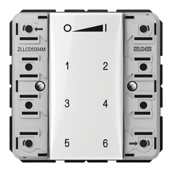
Device components
(1) LED
The LED of the respective side of the button lights up green as long as the button is
pressed.
When the functions "Individually set luminaires" or "Service functions" are active, both
LEDs light up red.
During commissioning, the LEDs indicate the status of the functions, see Chapter 4.
(2) Buttons for switching/dimming
(3) Scene buttons/functional buttons
(4) Cover
Intended use
-
ZigBee Light Link transmitter for operation of participants conforming with ZigBee Light
Link, e.g. lamps, luminaires, light bands, ballast units, adapters
32596203
J0082596203
Figure 1
1/17
23.05.2016
Advertisement
Table of Contents

Subscribe to Our Youtube Channel
Related Manuals for Jung ZLLCD5004M


Summary of Contents for Jung ZLLCD5004M
-
Page 1: Safety Instructions
ZigBee radio transmitter module 4-gang ZigBee radio transmitter module 4-gang Art. No. : ZLLCD5004M ZigBee radio transmitter module 4-gang Art. No. : ZLLLS5004M ZigBee radio transmitter module 4-gang Art. No. : ZLLA5004M Operating instructions 1 Safety instructions Electrical devices may only be mounted and connected by electrically skilled persons. -
Page 2: Basic Functions
ZigBee radio transmitter module 4-gang The transmitter can cooperate with ZigBee Light Link devices or systems of other manufacturers, e.g. Philips Hue or Osram Lightify. Surface-mounted installation in interior areas i Hereinafter, the participants will be called luminaires. Product characteristics Supports the adjustment of: brightness, colour temperature, light colour and colour saturation Corresponds with the ZigBee Light Link specification... - Page 3 ZigBee radio transmitter module 4-gang Figure 3 Press the corresponding scene button Ƈ briefly until ƌ. The luminaires that belong to that scene will switch to the saved values. 2.3 Saving scenes i If the scene shall be recalled from several transmitters, it must be saved at each transmitter separately.
- Page 4 ZigBee radio transmitter module 4-gang 3 Setting luminaires individually 3.1 Selecting a luminaire Figure 5 Simultaneously press the Ɔ and ƍ buttons shortly. Both LEDs light up red. All luminaires that are connected to the transmitter are selected. The luminaires acknowledge this by e.g.
- Page 5 ZigBee radio transmitter module 4-gang 3.2 Switching or dimming luminaires individually Figure 6 Select a luminaire, see chapter 3.1. Switch: Short press on Ɔ or ƍ button. Dim: Long press on Ɔ the or ƍ button. The dimming process ends when the button is released.
- Page 6 ZigBee radio transmitter module 4-gang 3.4 Setting the colour saturation Figure 8 Select a luminaire, see chapter 3.1. Setting white: shortly press Ɖ. Setting the maximum colour saturation: shortly press Ɗ. Setting individual colour saturations: press the Ɖ or Ɗ button until the desired colour saturation is set.
- Page 7 ZigBee radio transmitter module 4-gang 4 Commissioning 4.1 Basic commissioning procedure Preconditions: During commissioning, the respective devices must have a distance of 10 to 50 cm to each other. Each device can only be part of one network. The luminaire shall be operated using a Philips Hue Bridge or an Osram Lightify Gateway and transmitters.
- Page 8 ZigBee radio transmitter module 4-gang 4.2 Connecting a luminaire to a transmitter Figure 10 Press the Ɔ and ƌ buttons simultaneously until the LEDs flash green. The luminaire flashes briefly. Connection in process. LEDs on transmitter light up green. Lamp lights up green or flashes twice. Connection has been set up successfully.
- Page 9 ZigBee radio transmitter module 4-gang Within 10 seconds. start a connection process on a transmitter from the existing network (see chapter 4.2 or the manual of the respective transmitter). i After 10 seconds, if no connection process is started, the transmitter will search an open network in order to join it.
- Page 10 ZigBee radio transmitter module 4-gang Figure 13 Keep the Ƈ and ƈ buttons pressed until the LEDs flash green. Lamp flashes: Reset in progress. LEDs light up green; lamp lights up. Resetting successful. LEDs flash red quickly for 3 seconds. Participant could not be reset. 4.6 Deleting connections from the transmitter to the luminaires i The transmitter can save a maximum of 10 connections to luminaires.
-
Page 11: Service Functions
ZigBee radio transmitter module 4-gang 4.7 Resetting the transmitter to the default setting i All connections to luminaires will be disconnected and the allocation to a network will be deleted. Figure 15 Keep the Ɖ and Ɗ buttons pressed. After approx. 10 seconds, the LEDs flash green. Release the Ɖ... - Page 12 ZigBee radio transmitter module 4-gang Figure 16 Switch on the service functions. To do so, shortly press the Ƌ and ƌ buttons. LEDs light up red. The service functions have been switched on. Save luminaires or connections in the buffer memory of the transmitter, see chapter 5.2, 5.3 or 5.4.
- Page 13 ZigBee radio transmitter module 4-gang The luminaires saved in the buffer memory light up shortly. Within 2 minutes, after the last button has been pressed, transfer the buffer memory to the desired transmitter, see chapter 5.5. 5.3 Accepting connections from another transmitter Figure 18 Switch on the service functions, see chapter 5.1.
-
Page 14: Updating Device Software
ZigBee radio transmitter module 4-gang Switch on the service functions, see chapter 5.1. Press the Ƈ button for longer than 4 seconds. LEDs light up green for 3 seconds. The connections have been saved in the buffer memory. As an option, press the Ɔ button shortly in order to show all luminaires in the buffer memory. - Page 15 ZigBee radio transmitter module 4-gang Figure 21 Press the Ƌ and ƍ buttons simultaneously until the LEDs flash green. After 10 seconds the LEDs flash green quickly: The transmitter searches for an update. The LEDs flash red: Update in process. The LEDs flash green for 3 seconds: Update successful.
-
Page 16: Technical Data
ZigBee radio transmitter module 4-gang Screw wall transmitter module (8) to base plate. i Screwing the screws too tightly could impair functions of the wall transmitter. Snap on the buttons (11)(figure 22). Information on gluing mounting Precondition: To be able to fasten the wall transmitter safely, the surface must be flat and free of dust and grease. -
Page 17: Troubleshooting
Art. No. ..504TSA.. 8.4 Conformity Albrecht Jung GmbH & Co. KG hereby declares that the radio system type Art. No. ZLLCD5004M / ZLLLS5004M / ZLLA5004M corresponds to the directive 2014/53/EU. You can find the full article number on the device. The complete text of the EU Declaration of Conformity is available under the Internet address: www.jung.de/ce...
Need help?
Do you have a question about the ZLLCD5004M and is the answer not in the manual?
Questions and answers