Samsung RC090MHXEA Installation Manual
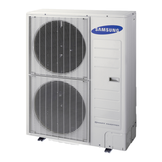
Rc-mhxga/rc-mhxea series air to water heat pump mono outdoor unit
Hide thumbs
Also See for RC090MHXEA:
- Service manual (53 pages) ,
- Installation manual (23 pages) ,
- Installation and maintenance manual (22 pages)
Table of Contents
Advertisement
Advertisement
Table of Contents
Troubleshooting

Related Manuals for Samsung RC090MHXEA


Summary of Contents for Samsung RC090MHXEA
- Page 1 EHS mono_RC***MHXGA_IM_E_34411A(3).indd 60 2012-11-26 오후 3:02:06...
-
Page 2: Installation Manual
Air to Water Heat Pump Mono Outdoor Unit installation manual imagine the possibilities Thank you for purchasing this Samsung product. To receive more complete service, please register your product at www.samsung.com/register E S F I P D DB98-34411A(3) EHS mono_RC***MHXGA_IM_E_34411A(3).indd 61... -
Page 3: Table Of Contents
In order to prevent electric shocks, fires or injuries, always stop the unit, disable the protection switch and contact SAMSUNG’s technical support if the unit produces smoke, if the power cable is hot or damaged or if the unit is very noisy. - Page 4 f Always remember to inspect the unit, electric connections, refrigerant tubes and protections regularly. These operations shall be performed by qualified personnel only. f The unit contains moving parts and electrical parts, which should always be kept out of the reach of children. f Do not attempt to repair, move, alter or reinstall the unit by unauthorized personnel, these operations may cause product damage, electric shocks and fires.
-
Page 5: Product Specifications
Product specifications Product line-up Line-up Remark Chassis Heat pump units RC120MHXEA RC120MHXGA RC140MHXEA Model name RC090MHXEA RC140MHXGA RC160MHXEA RC160MHXGA MIM-E03A Requisite Control kit Auxiliary parts Standard models: NH200CHXEA Option NH300CHXEA Cylinder unit Accessories f Keep supplied accessories until the installation is finished. - Page 6 RC120MHXEA RC140MHXEA RC160MHXEA Type Unit RC090MHXEA RC120MHXGA RC140MHXGA RC160MHXGA 1P, 220~240VAC 50Hz 1P, 220~240VAC 50Hz 1P, 220~240VAC 50Hz Power source 1P, 220~240VAC 50Hz 3P, 380~415VAC 50Hz 3P, 380~415VAC 50Hz 3P, 380~415VAC 50Hz Weight(Kg) Compressor Rotary inverter Rotary inverter Rotary inverter...
-
Page 7: Application Examples
• SAMSUNG can not be put responsible for incorrect or unsafe situations in the water system. Make sure that the boiler, radiators, convectors, solar collectors, UFHs, FCUs, additional pumps, pipings, and controls in the water system are in accordance with relevant local laws and regulations under the installer's responsibility. - Page 8 Mono outdoor + Cylinder unit RF Receiver Expansion Vessel Supply header Wired controller Return header From city water Control Kit (provided by SAMSUNG) Radiators or convectors Hot water Supply Room thermostat (Wireless) Room thermostat (option) (Wired) Supply header Return header Under-floor heating coils Indoor ...
-
Page 9: Main Components
Main components Dimensions(Overall) Heat pump for R410A. 1-Fan chassis f RC090MHX✴ (Unit : mm) 2-Fan chassis f RC120MHX✴/RC140MHX✴/RC160MHX✴ (Unit : mm) EHS mono_RC***MHXGA_IM_E_34411A(3).indd 8 2012-11-26 오후 3:01:49... - Page 10 RC120MHX/RC140MHX/RC160MHX Dimensions (Water pipe) RC090MHX RC120MHX/RC140MHX/RC160MHX RC090MHX✴ RC120MHX✴/RC140MHX✴/RC160MHX✴ RC090MHX 513.4 513.4 151.5 244.4 151.5 244.4 83.5 83.5 (Unit : mm) (Unit : mm) (Unit : mm) (Unit : mm) (Unit : mm) (Unit : mm) EHS mono_RC***MHXGA_IM_E_34411A(3).indd 9 2012-11-26 오후 3:01:53...
- Page 11 Main components RC090✴ ③ ② ① Name Note. ① ② Base heater SUS316L, 150W ③ Water fitting BSPP 1" Male EHS mono_RC***MHXGA_IM_E_34411A(3).indd 10 2012-11-26 오후 3:01:53...
- Page 12 RC120✴/RC140✴/RC160✴ ① ④ ⑤ ③ ② Name Note. ① ② Base heater SUS316L, 150W ③ Water hose in Rubber hose ④ Water hose out Rubber hose ⑤ Water fitting BSPP 1" Male EHS mono_RC***MHXGA_IM_E_34411A(3).indd 11 2012-11-26 오후 3:01:53...
-
Page 13: Functional Diagram
Functional diagram RC090MHX✴/RC120MHX✴/RC140MHX✴/RC160MHX✴ 4WAY T/S #6 HP s/w T/S #1(TW1) T/S #2(TW2) T/S #4 T/S #3 Comp Accum T/S #5 Exp. v/v Filter Filter Part Description Plate heat exchanger T/S #1 For water outlet temp sensor T/S #2 For water inlet temp sensor T/S #3 For PHE out temp T/S #4... -
Page 14: Installing The Unit
Installing the unit Moving the outdoor unit f Select the moving route in advance. f Be sure that moving route is safe from weight of the outdoor unit. f Do not slant the product more than 30˚when carrying it. (do not lay the product down sideways) f The surface of the heat exchanger is sharp. - Page 15 Installing the unit Deciding on where to install the outdoor unit Decide the installation location regarding the following condition and obtain the user’s approval. f The outdoor unit must not be placed on its side or upside down, as the compressor lubrication oil will run into the cooling circuit and seriously damage the unit.
- Page 16 f Do not install the Air to Water Heat Pump in following places. • The place where there is mineral oil or arsenic acid. There is a chance that parts may get damaged due to burned resin. The capacity of the heat exchanger may reduce or the Air to Water Heat pump may be out of order. • The place where corrosive gas such as sulfurous acid gas generates from the vent pipe or air outlet.
- Page 17 Installing the unit Space requirements for outdoor unit When installing 1 outdoor unit (Unit : mm) ❋ When the air outlet is opposite the wall ❋ When the air outlet is towards the wall 2,000 or more 300 or more 600 or more ❋...
- Page 18 When installing more than 1 outdoor unit (Unit : mm) ❋ When the air outlet is towards the wall 300 or more 600 or more 600 or more 600 or more ❋ When 3 sides of the outdoor unit are blocked by the wall 300 or more 300 or more 600 or more...
-
Page 19: Outdoor Unit Installation
Installing the unit Outdoor unit installation The outdoor unit must be installed on a rigid and stable base to avoid any increase in the noise level and vibration, particularly if the outdoor unit is to be installed in a location exposed to strong winds or at a height, the unit must be fixed to an appropriate support(wall or ground). -
Page 20: Drain Work
Drain work While Air-Water Heat Pump is running in heating mode, Ice can begin accumulate on the surface of condenser. To prevent Ice from growing, system go into De-frost mode and then Ice on the surface changes to water. Dropped water from condenser shall be eliminated through running drain holes to prevent Ice growing at low temperature. f In case there is not enough space for drainage out of the unit, additional drain works are required. - Page 21 Installing the unit Selecting a location in cold climates • When operating the unit in a low outdoor ambient temperature, be sure to follow the instructions described below. NOTE f To prevent exposure to wind, install the unit with its suction side facing the wall. f Never install the unit at a site where the suction side may be exposed directly to wind.
-
Page 22: Piping Work
Piping work Water connections must be made in accordance with the outlook diagram delivered with the unit, respecting the water in- and outlet. If air, moisture or dust gets in the water circuit, problems may occur. Therefore, always take into account the following when connecting the water circuit: f Use clean pipes only. - Page 23 Piping work • Before installing/commissioning the unit, make sure to check the following points : CAUTION - The maximum water pressure of the unit is 2.8 bar static pressure. - The operating range of water temperature is 15~55˚C at heating conditions and 5~25˚C at cooling conditions.
-
Page 24: Freeze Protection
Freeze protection Frost can make some damage on the hydraulic system. It is because it is installed outside house nomally. To avoid taking risks of freezing problem, special cares such as Anti-freezing fluid are required as below. Ethylene glycol concentration can vary depeding on outdoor temperature where our system is installed, fill in Ethylene glycol by mixing as below. - Page 25 Piping work Unit resistance and PHE resistance by glycol concentrate The unit is composed of water pipes and PHE basically. To ensure correct operation and predict the expected performance, Flow and Resistance table can be used and Flow and Resistance characteristic is dependent on Glycol concentration. RC090✴✴...
-
Page 26: Flow Switch
Flow switch is provided by Samsung control kit as a sub component. • Flow switch shall be installed described by installation manual of Mono unit or Control kit. • All electric wiring works shall be implemented by manuals which Samsung provided. CAUTION • Before completing the installation works, make sure to check if the flow switch is installed in horizontal and... - Page 27 Piping work Pressure relief valve MONO Unit does not have a pressure relief valve. The valve shall prevents abnomal water pressure from damaging the the system by opening at 3.0 bar. • Make certain that the discharged water out of drain pan does not affect other elements. CAUTION Filter / Strainer Installation of Filter / Strainer is mandatory for water system.
-
Page 28: Wiring
Wiring Two electronic cables must be connected to the outdoor unit. f The connection cord between indoor unit and outdoor unit. f The power cable between outdoor unit and auxiliary circuit breaker. f Specially for Russian and European market, before installation, the supply authority should be consulted to determine the supply system impendance to ensure compliance. - Page 29 Fuse cut-off Rated Voltage Range current Outdoor unit Maximum MCA✴1.25 + Volts Current in normal Total fuse in unit Additional Load operation RC090MHXEA 220-240 22 A 27.5 A 40 A RC120MHXEA 220-240 28 A 35 A 40 A RC140MHXEA 220-240 30 A 37.5 A...
- Page 30 3 Phase Fuse cut-off Rated Voltage Range current Outdoor unit Maximum MCA✴1.25 + Volts Current in normal Total fuse in unit Additional Load operation RC120MHXGA 380-415 10 A 12.5 A 25 A RC140MHXGA 380-415 11 A 13.8 A 25 A RC160MHXGA 380-415 12 A...
- Page 31 Wiring Between indoor unit and outdoor unit connection cable specifications(Common in use) Communication cable Home server 0.75mm², 2wires 0.75mm², 2wires f For Indoor Power Cable, use the grade H07RN-F or H05RN-F materials. When installing the indoor unit in a computer room or network room, use the double shielded (Tape aluminum / polyester braid + copper ) cable of FROHH2R type.
- Page 32 Wiring diagram of power cable When using ELB for 1 phase and 3 phase f 1 phase Cable tie Power Supply Electrical component box MCCB Main power cable Communication cable MCCB f 3 phase L1(R) L2(S) L3(T) Indoor Unit Cable tie f The appearance of the unit may be different from the picture depending on the model.
- Page 33 Wiring Wiring diagram of connection cord 1 phase 3 phase Control kit Control kit L1(R) L2(S) L3(T) Cable Cable Communication Main power cable Communication cable 3 Phase 4 Wires power cable cable (AC 380V) • Lay the electrical wiring so that the front cover does not rise up when doing wiring work and attach the front cover securely.
- Page 34 Nominal dimensions for 4/6 (0.006/0.009) 10 (0.01) 16 (0.02) 25 (0.03) 35 (0.05) 50 (0.07) 70 (0.10) cable [mm2(inch)] Nominal dimensions for 4 (3/8) 8 (3/16) 8 (3/16) 8 (3/16) 8 (3/16) 8 (3/16) 8 (3/16) 8 (3/16) screw [mm(inch)] Standard dimension 16.5 9.5 (3/8) 15 (9/16) 15 (9/16)
-
Page 35: Testing Operations
Testing operations 1. Check the power supply between the outdoor unit and the auxiliary circuit breaker. • 1 phase power supply : L, N • 3 phases power supply : R,S,T,N 2. Check the CONTROL KIT 1) Check that you have connected the power and communication cables correctly. (If the power cable and communication cables one mixed up or connected incorrectly, the PCB will be damaged.) 2) Check the temp. - Page 36 Display Number of Display contents Units press Segment 1 Segment 2 Segment 3 Segment 4 Not used exchanger capacity Protection Frequency state control 0 : Normal 0 : no protection 1 : Hold control 0 : air 2 : Down conditioning 1 : freezing Protection control...
-
Page 37: Trouble Shooting
Trouble shooting • Incorrect handling of thermostat, safety valve or other valves may lead to tank rupture. When servicing the unit follow instructions carefully: WARNING • Always turn off main power supply when water supply is being shut off. • Test the free operation of the safety valve regularly by opening the valve ensuring the water flows freely. • Electrical connection and all servicing of the electrical components should only be carried out by an authorized electrician. - Page 38 Display Explanation Error Source [Inverter] IPM over current error OUTDOOR UNIT Compressor V limit error OUTDOOR UNIT DC LINK over/low voltage error OUTDOOR UNIT [Inverter] Compressor rotation error OUTDOOR UNIT [Inverter] Current sensor error OUTDOOR UNIT [Inverter] DC LINK voltage sensor error OUTDOOR UNIT EEPROM read/write error OUTDOOR UNIT...
-
Page 39: Maintenance
Maintenance Listed checks and inspections shall be implemented regularly so that the unit can operate as design intention in production site. Always switch off the unit and remove power cable from the electric source before carrying out any maintenance or repair works. - Page 40 To run the units properly, keep the amount of refrigerant which SAMSUNG designated. Procedures as below is describing how to adding the amount of refrigerant.
-
Page 41: Cylinder Unit
Cylinder unit Safety information (Before installing a cylinder unit, please read this manual thoroughly to ensure that you know how to safely and efficiently install a new appliance.) WARNING • If you don’t follow the safety precautions, you may get the risk of serious wound or death. f The installation must be done by the manufacturer or its service agent or a qualified person in order to avoid a hazard. -
Page 42: General Information
General information f SAMSUNG Eco Heating system with cylinder unit is designed to withstand SAMSUNG durability and reliability requirements. We cannot guarantee neither good operation nor reliability of total system with other brand tanks. f The piping, valves and system configuration of cylinder unit should be followed a relevant local or national regulations. - Page 43 ① ② ⑨ ⑪ Part Water pump Wilo Motorized 2 Way valve Honeywell V4043 Control kit Samsung RF Receiver Wired remote controller Samsung Installed Air vent Combination valve Expansion relief valve Tundish Ø15 x Ø22 mm Temperature and pressure relief valve...
- Page 44 Detailed views 1.1/2"BSP X 3/4"BSP (female) ADAPTER 1.1/2"BSP X 3/4"BSP (female) ADAPTER 1/2"BSP 3/4"BSP (female L=70mm) 3/4"BSP (female L=70mm) 1/2"BSP 3/4"BSP (female L=70mm) 3/4"BSP (female L=70mm) 3/4"BSP Recirc. ANODE ① 1/2"BSP ② ③ ⑤ ⑧ 5/4"heater ⑥ 5/4"heater ⑦ 420/630 3/4"BSP ④...
-
Page 45: Flow Diagram
Cylinder unit Flow diagram From City Water From heat pump Hot water Supply (a Public Water Supply) Water pump Supply Header To heat pump Return Header Electric Heater, 3kW To radiators Heat pump unit Water pump To UFHs Supply Header Return Header From both radiators and UFHs From heat pump... - Page 46 Water tank specifications Detailed information for the DHW Tank are described in the following table. Standard Description Unit NH200CHXEA NH300CHXEA Material quality AISI 444 / DIN 1.4521 Pressure vessel Volume capacity ℓ Capacity Electric element Material INCOLOY 825 Voltage V/Hz 1P, 240~, 50Hz Material quality Duplex LDX 2101...
- Page 47 Cylinder unit Standard Description Unit NH200CHXEA NH300CHXEA Vessel 585 x 1130 585 x 1580 Dimensions 692 x 702 x 1200 692 x 702 x 1600 Packing 800 x 900 x 1600 800 x 900 x 2050 Cold water inlet(city water) ø22mm pipe ø22mm pipe Flow from Heat Pump...
-
Page 48: Space Requirements
Space requirements Positions of water inlet and outlet pipe are affected by the layout of cylinder unit. The layout of pipes and other components except cylinder unit are the responsibility of installers. The cylinder unit must be laid out in accordance with the illustrations as below to prevent any water leakage and malfunction. - Page 49 Cylinder unit Wiring diagram • Turn on the cylinder unit and outdoor unit after completing electric wiring works. • Do not disassemble the wirings out of the unit while the unit is operating. CAUTION • Circuit breaker shall be installed for safety and maintenance . • Fill the cylinder unit with water before turning on electric power.
-
Page 50: Immersion Heater
Immersion heater Cylinder is provided with a single immersion heater located above the heating coil. The element is designed as an auxiliary heater to supplement the energy from the heat pump if this is insufficient to heat the domestic water to the required level. Wiring instructions for the immersion heater is located on the reverse side of the lower lid. - Page 51 Cylinder unit Switch box layout Control Kit EHS mono_RC***MHXGA_IM_E_34411A(3).indd 50 2012-11-26 오후 3:02:05...
-
Page 52: Installation
Installation Moving the cylinder unit f Select the moving route in advance. f Be sure that moving route is safe from weight of the cylinder unit f Do not slant the product more than 30º when carrying it. Moving the cylinder unit with a fork lift. f Insert the fork into the wooden pallet at the bottom of the cylinder unit carefully. - Page 53 Installation Secondary Circulation f Cylinder unit can be used with secondary circulation. An appropriate WRAS approved bronze circulator should be used in conjuction with a non-return valve to prevent backflow. f Secondary circulation system it may be necessary to incorporate an extra expansion vessel into the circuit to accommodate the increased system water volume.
- Page 54 Discharge Arrangement Typical Discharge Pipe Arrangement 15 mm discharge pipe 600 mm max. P & T Relief Valve Dotted line showing alternative route with single tundish being used 300 mm min. Discharge below fixed grating 22 mm metal pipe with continuous fall up to 9m equivalent length (D2).
-
Page 55: Worked Example
Installation Examples of acceptable discharge arrangements are: 1. Ideally below the fixed grating and above the water seal in trapped gulley. 2. Downward discharges at a low level: i.e. up to 100mm above the external surfaces such as car parks, hard standings, grassed area etc are acceptable providing that where children play or otherwise come into contact with discharges, a wire cage or similar guard is positioned to prevent contact whilst maintaining visibility. -
Page 56: Troubleshooting
Troubleshooting FAULT POSSIBLE CAUSE REMEDY No water flow from hot taps. 1. Mains supply off. 1. Check and open stopcock. 2. Strainer blocked. 2. Turn off water supply. Remove strainer and clean. (See Pressure Reducing Valve page 6 Installation Manual) 3. - Page 57 Troubleshooting No water flow from hot taps Line strainer blocked Mains supply off Cold water PRV incorrectly fitted Clear line strainer Open supply valve Check and refit as required If problem still persists contact a competent engineer Intermittent water discharge Reduced Internal expansion Thermal control failure volume...
- Page 58 Hot water from taps is cold Indirect Heating Immersion Heater Is the programmer Is the boiler Are immersion Has immersion set to central working heaters switched heater thermal cut- heating or not out operated? switched on Switched on Check and reset Check and set Is the Has cylinder...
-
Page 59: Commissioning
Commissioning Filling up 1. Open a hot tap. 2. Open the cold water supply valve. 3. When water flows from hot tap, close the tap. 4. Allow the system to stabilize for 5 minutes. 5. Open each hot water tap in turn to expel air from the system pipe work. 6. -
Page 60: Maintenance
Maintenance It is recommended that annually a competent person a Inspects and cleans the line strainer. b Checks the operation of the expansion relief valve and temperature & pressure relief valve. c Recommissions the cylinder in accordance with the instructions. Corrosion resistance Duplex stainless steel is naturally corrosion resistant to mains water supply.
Need help?
Do you have a question about the RC090MHXEA and is the answer not in the manual?
Questions and answers