Table of Contents
Advertisement
Quick Links
Advertisement
Table of Contents

Related Manuals for Samsung Hydro Unit AE090RNYD Series


Summary of Contents for Samsung Hydro Unit AE090RNYD Series
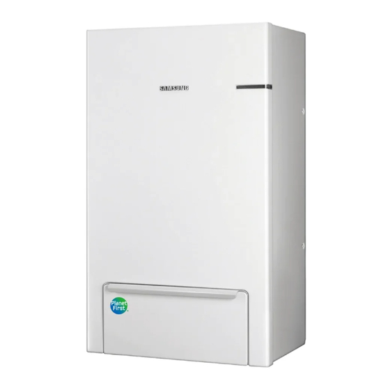
- Page 1 Air to Water Heat Pump Installation manual Hydro Unit AE090RNYD** • Thank you for purchasing this Samsung Product. • Before operating this unit, please read this installation manual carefully and retain it for future reference. DB68-08552A-04...
-
Page 2: Table Of Contents
Business users should contact their supplier and check the terms and conditions of the purchase contract . This product and its electronic accessories should not be mixed with other commercial wastes for disposal . For information on Samsung’s environmental commitments and product-specific regulatory obligations, e . g . REACH, visit: www . s amsung . c om/uk/aboutsamsung/sustainability/environment/our-commitment/data/... -
Page 3: Safety Precautions
. f This manual explains how to install an indoor unit with a split system with two SAMSUNG units . The use of other types of units with different control systems may damage the units and invalidate the warranty . The manufacturer shall not be responsible for damages arising from the use of non compliant units . - Page 4 Safety precautions INSTALLING THE UNIT IMPORTANT: When installing the unit, always remember to connect first the refrigerant tubes, then the electrical lines . Always disassemble the electric lines before the refrigerant tubes . f Upon receipt, inspect the product to verify that it has not been damaged during transport . If the product appears damaged, DO NOT INSTALL it and immediately report the damage to the carrier or retailer (if the installer or the authorized technician has collected the material from the retailer .
- Page 5 Safe parts are the ones with which the worker can work in a flammable atmosphere . Other parts may result in ignition due to leakage . f Replace components only with parts specified by Samsung . Other parts may result in the ignition of refrigerant in the atmosphere from a leak .
- Page 6 Safety precautions Leakage detection methods f The leakage detector shall be calibrated in a refrigerant-free area . f Make sure that the detector is not a potential source of ignition . f The leakage detector shall be set to the LFL (lower flammability limit) . f The use of detergents containing chlorine shall be avoided for cleaning because the chlorine may react with the refrigerant and corrode the pipings .
-
Page 7: Installation Location Requirements
Installation location requirements f The unit shall be installed in an open space that is always ventilated . f The local gas regulations shall be observed . f For installation inside a building (this applies either to indoor or outdoor units installed inside) a minimum room floor area of space conditioned is mandatory according to IEC 60335-2-40:2018 (see the reference table into either the indoor or outdoor unit installation manual) . -
Page 8: Product Specifications
Product specifications Product compatibility Line-up Chassis Outdoor units AE040RXED** Model Name AE090RXED** AE060RXED** Hydro Units Indoor units Model Name AE090RNYD** ENGLISH-8... - Page 9 Accessories Installation Manual(1) User Manual(1) Pattern Sheet(1) Service Valve(2) Wall Mounting Bracket(1) Ring band (1) Temperature Sensor for DHW Tank Temperature Sensor for Mixing Valve Zone Sensor (1x10m, WHT) (2) (1x15m,YEL) (1) (1x15m, BLU) (1) Sensor holder of zone sensor and Sensor clip for zone sensor and mixing Cable-tie for zone sensor and mixing mixing valve sensor (3)
- Page 10 Product specifications Specifications Type Unit AE090RNYDEG AE090RNYDGG Power Source V/Hz 1ø, 220-240 V~, 50 Hz 3ø, 380-415 V~, 50 Hz Cooling °C 5~25 5~25 Operation Range [Water] Heating °C 15~65 15~65 Cooling dB(A) Sound Pressure Heating dB(A) Sound Power Heating dB(A) 850 x 510 x 315 850 x 510 x 315 Dimension (HxWxD)
-
Page 11: Typical Application Examples
Typical application examples • The application examples given below are for illustration purposes only . • When the SAMSUNG Air-to-Water Heat Pump system is used in series with another heat source (e . g . gas boiler), WARNING ensure that the return water temperature not exceed 65 °C . - Page 12 *) We control only the on / off signal of backup boiler according to outdoor temperature . Backup boiler should be installed with own device according to the field condition . • Samsung has not responsible for performance and stability of backup boiler . CAUTION...
-
Page 13: Main Components
Main components ㉑ ① ⑳ ② ③ ⑲ ④ ⑤ ⑱ ⑥ ⑰ ⑦ ⑧ ⑯ ⑮ ⑨ ⑭ ⑬ ⑩ ⑫ ⑪ Name Note ① Air vent 3/8” BSPP male 3/8” ② Backup heater thermal fuse Thermal cut out 94 °C (+0, -6 °C) ③... -
Page 14: Functional Diagram
Functional diagram ⑦ ⑥ ⑤ ⑬ ③ ④ ⑨ ⑧ ⑫ ⑭ ⑩ ② ⑪ ① Note ① Service valve(R) ② Strainer ③ Flow Sensor ④ Heat exchanger ⑤ Backup heater ⑥ Pressure relief valve ⑦ Air-vent valve ⑧ Variable Speed water pump ⑨... -
Page 15: Dimensional Drawing
Dimensional drawing 314 . 6 103 . 7 78 . 5 131 . 7 Gas pipe (O.D.) Liquid pipe (O.D.) Water Inlet Water Outlet Indoor unit 15 . 8 8 mm (5/8 inch) 9kW : 6 . 3 5 mm (1/4 inch) BSPP male 1 1/4" BSPP male 1 1/4"... -
Page 16: Installing The Unit
Installing the unit Installation of the indoor unit The indoor unit should be installed indoors and meet the following conditions . f Installation site should be sheltered from frost . f In area with suitable space for servicing . f A place with adequate ventilation . f Where there is no risk of leakage of flammable gases . -
Page 17: Mounting The Indoor Unit
Mounting the indoor unit ❋ ❋ A minimum of two people should lift the unit by the handles and not by the drain pan or pipe work . Handle f Drill 6 holes from the pattern sheet for fixing the wall bracket and unit . After completing holes, detach the pattern sheet . f Fix the wall-mount-bracket to the wall using appropriate plugs and screws(Use over M8 6 screws) . -
Page 18: Pipe Work
Pipe work Refrigerant pipe work For all guide lines, specifications regarding refrigerant pipe work between the indoor unit and the outdoor unit, please follow the outdoor unit installation manual . Tightening Gas pipe (O . D . ) Liquid pipe (O . D . ) Final Torque Torque Indoor unit... -
Page 19: Water Pipe Work
Water pipe work The hydro unit is equipped with components listed on the table below . The hot and cold water supply connections are clearly marked on the unit with labels . And service valves are provided . Whole water plumbing system including Hydro unit shall be installed by a qualified technician and must comply with all relevant European and national regulations . -
Page 20: Flushing And Air-Purging
Pipe work Flushing and air-purging When filling water, the following start-up procedure should be followed . 1 . All system components and pipes must be tested for the presence of leaks . 2 . Make-up water assembly or Flushing unit is recommended for installation and service . 3 . - Page 21 ESP(External Static Pressure) Diagram The illustration below shows the external static pressure of the unit depending on the water flow and the pump setting . ESP [kPa] Flow [l/min] 2526 4546 Water flow rate : 26 LPM If the pressure loss of total system is over 43 kPa , additional water pump should be installed in series . Otherwise, the flow rate might be decreased, causing insufficient heating or cooling .
- Page 22 Pipe work PWM characteristic curve Max . PWM input signal(%) The additional pump should be the same type of product as the above graph . Recommendation GRUNDFOS UPM3 25-75 Case 2) AC pump Only a single additional AC pump is is allowed . 1 .
- Page 23 Setting the pre-pressure of the expansion vessel When it is required to change the default pre-pressure of the expansion vessel(1 bar), keep in mind the following guidelines: f Use only dry nitrogen to set the expansion vessel pre-pressure . f Inappropriate setting of the expansion vessel pre-pressure will lead to malfunction of the system . Therefore, the pre- pressure should only be adjusted by a licensed installer .
-
Page 24: Charging Water
Pipe work Charging water After installation is completed the following procedures shall be used to charge water into the hydro unit . f Connect water lines to water connections of hydro unit . f The air-vent valve shall be opened at least 2 turns and drain valves shall be closed . -
Page 25: Wiring Work
Wiring work • Field-supplied electrical components such as power switch, circuit breakers, wires, terminal blocks, etc must be properly chosen with compliance with national legislation or regulation . CAUTION • Switch off the power supply before making any connections . •... - Page 26 Wiring work Part code Part name Terminal Terminal description #1: L AC INPUT ① TB-A AC POWER-IN #2: N AC INPUT #1: L AC OUTPUT ② HEATER OUT TB-A1 #2: N AC OUTPUT #1: N AC OUTPUT #2: MIXING VALVE_CW (L) AC OUTPUT #3: MIXING VALVE_CCW (L) AC OUTPUT...
- Page 27 Part code Part name Terminal Terminal description #1: DC 12V DC OUTPUT #2: NO CONNECT #3: NO CONNECT ⑨ CNS201 DISPLAY #4: NO CONNECT #5: GND DIGITAL GROUND #6: LED CONTROL SIGNAL DC OUTPUT #7: NO CONNECT 2-WIRE ⑩ CNS313 COMMUNICATION #1: WATER PUMP PWM SIGNAL DC OUTPUT...
- Page 28 Wiring work Part code Part name Terminal Terminal description #1: Flow Sensor DC INPUT ㉓ CNS041 Flow Sensor #2: GND DIGITAL GROUND #1: HEATER TEMP . (10kΩ @ 25 °C) DIGITAL INPUT #2: GND DIGITAL GROUND #3: EVA-OUT TEMP . (10kΩ @ 25 °C) DIGITAL INPUT #4: GND DIGITAL GROUND...
- Page 29 Part code Part name Terminal Terminal description #1: SG READY1 SIGNAL DC INPUT #2: OPTION TEMP . ( 10kΩ @ 25 °C) DIGITAL INPUT #3: GND DIGITAL GROUND #4: GND DIGITAL GROUND #5: SG READY2 SIGNAL DC INPUT #6: ZONE2 TEMP . (10kΩ @ 25 °C) DIGITAL INPUT #7: GND DIGITAL GROUND...
- Page 30 Wiring work Part code Part name Terminal Terminal description Terminal Min . / Max . Function Input /output Description Remark No . current B2/B3/B5 Mixing valve AC 230V output 10 mA / 50 mA Mixing Valve operation(B2: CW, B3: CCW) Option Signal output for Backup Boiler(B5: B4/B5...
- Page 31 Wiring diagram 1-Phase Wiring diagram 3-Phase * It does not support external input(CNS083)/output(CNS081) signal function ENGLISH-31...
-
Page 32: Selecting Solderless Ring Terminal
Wiring work Selecting solderless ring terminal f Select a solderless ring terminal of a connecting power cable based on a nominal dimensions for cable . f Cover a solderless ring terminal and a connector part of the power cable and then connect it . Nominal Nominal Standard... - Page 33 Torque requirements CONTROL-KIT PBA M3.5 M3.5 Tightening torque Screw size Part Terminal code Remarks (N·m) PV/Peak power control Dry contact input SIGNAL Control Kit PBA 0 . 5 ~0 . 7 5 2P Terminal Block R-32 ALARM Dry contact output WATER PUMP PWM signal output Control Kit PBA...
- Page 34 Wiring work C-BOX: SINGLE PHASE C-BOX: 3 PHASE Tightening torque Screw size Part Terminal code Remarks (N·m) 0 . 5 ~0 . 7 5 20P Terminal Block 1~20 Digital input/output Magnetic contactor 2P AC 220V-240V power Single phase input/output Magnetic contactor 3P AC 380V-415V power 3phase input/output...
-
Page 35: Grounding Work
Grounding work f Grounding must be done by a qualified installer for your safety . Grounding the power cable f The standard of grounding may vary according to the rated voltage and installation place of a heat pump . f Ground the power cable according to the following . Installation place High humidity Average humidity... -
Page 36: Checking Correct Grounding
Wiring work Checking correct grounding If the power distribution circuit does not have a grounding or the grounding does not comply with specifications, an grounding electrode must be installed . The corresponding accessories are not supplied with the Air to Water Heat pump . 1 . -
Page 37: Communication Cable Connection
2 wires for communication cable Circuit breaker Communication cable between indoor and outdoor units Communication cable Earth CONTROL-KIT PBA TB-C TB-A TB-A1 Hydro unit Communication cable connection CONTROL-KIT PBA TB-C TB-A TB-A1 1 . 1 phase product 1Φ, 220-240Vac Distribution board MCCB + ELB ELCB grounding... -
Page 38: Connecting The Power Terminal
Wiring work 2 . 3 phase product 3Φ, 380-415Vac Distribution board MCCB + ELB ELCB grounding L1(R) L2(S) L3(T) L1(R) L2(S) L3(T) 3 phase AC 3 phse AC POWER POWER-IN 380~415V~ grounding • If the supply cable is damaged, it must be replaced by a special cable or assembly available from the manufacturer or installer . -
Page 39: Connection Of The Backup Heater Power Supply
Cable tie Solderless terminal Thin cable Thick cable Separate the solderless terminal up and down to prevent it being get loosen . Place the thin cable upward and the thick cable downward . Secure the power cable with the cable tie . Tightening Torque (kgf •... - Page 40 Wiring work Connection of the thermostat Description No. of wires Max. current Thickness Supply Scope > 0 . 7 5 mm , H05RN-F or Field supply (220-240V~, Room Thermostat 22mA H07RH-F Input) 1 . Before the installation, hydro unit should be turned off . 2 .
- Page 41 Connection of the water pump for 2-zone control (FSV 4061=1) f Zone1 water pump connection: B10(L1) + B11(N) f Zone2 water pump connection: B14(L1) + B15(N) Zone2 Tw2_z2 Balancing vessel Radiator Zone1 Tw2_z1 Under Floor ENGLISH-41...
- Page 42 Wiring work B11 - Neutral AC power output for Zone1 water pump control signal B10 - Live AC power output for Zone1 water pump control signal Neutral additional pump Live additional pump Terminal block Pump Power • The maximum allowable current that this terminal block can supply for the additional water pump is 50mA . CAUTION B15 - Neutral AC power output for Zone2 water pump control signal B14 - Live AC power output for Zone2 water pump control signal...
- Page 43 Connection of the 3-way valve Description No. of wires Mini. / Max. current Thickness Supply Scope Diverting type 3way > 0 . 7 5 mm , H05RN-F or Field supply (220-240V~, 10mA / 50mA valve H07RN-F Input) Status 3-way diverting valve for water tank f When cooling operating mode, floor heating loops (Initial) will be closed .
- Page 44 Wiring work Connection of the back-up boiler Description No. of wires Mini. / Max. current Thickness Supply Scope 0 . 7 5mm H05RN-F or Field supply (220-240V~, Back-up Boiler 2+ground 10mA / 50mA H07RN-F Input) 1 . Before the installation, hydro unit should be turned off . 2 .
- Page 45 Connecting for smart grid ready control 9 10 11 12 13 14 15 16 17 18 19 20 Connection terminal for Connection terminal SG READY Signal 2 for SG READY Signal 1 SG READY Signal 2 SG READY Signal 1 SG READY Signal 1 SG READY Signal 2 Product operation...
-
Page 46: Self-Test Mode Of Wired Remote Controller
Self-test mode of wired remote controller Use of self-test mode Service mode Service mode Reset All Service Mode Power Master Reset ODU K3 Reset Field Setting Value Self-Test Mode Indoor Unit Option Please enter your PASSWORD 1 . If you want to use the various additional functions for your Wired Remote Controller, press the buttons at the same time for more than 3 seconds . -
Page 47: Troubleshooting
Troubleshooting If the unit has some problem to work properly, the LED on hydro unit will flash and some error codes will be displayed on the controller . The following table described the explanation of error codes on the LCD display . Thermistor f Check its resistance . - Page 48 Troubleshooting Communication Display Explanation Communication error between remote controller and the Hydro unit Tracking error between remote controller and the Hydro unit Memory(EEPROM) Read/Write Error(Wired remote controller data error) E601, E604 E654 MEMORY(EEPROM) Read/Write Error (Wired controller data error) Micro SD card Download connector EEPROM F3(COM2_B)/F4(COM2_A)
- Page 49 Water pump & Flow Sensor Display Explanation Low flow rate error • in case of low flow rate in 30 sec during water pump signals is ON(Starting) • in case of low flow rate in 15 sec during water pump signals is ON(After starting) Normal flow rate error •...
-
Page 50: Dhw Tank
DHW tank DHW tank should be purchased separately (not supplied) . Safety information Before installing an DHW Tank, please read this manual thoroughly to ensure that you know how to safely and efficiently install a new appliance . • If you don’t follow the safety precautions, you may get the risk of serious wound or WARNING death . -
Page 51: Piping Diagram
Piping diagram • The product must be installed without any water leakage . • Please verify that the DHW tank and other components are properly installed and reinstall them if necessary . CAUTION - Use certified components and the correct tools . - Make sure there is sufficient installation space . -
Page 52: System Configuration
For the reliable performance and durability, all parts as listed below ,including a relief valve, an expansion vessel, a drain valve and pressure reducing valve, should be installed according to each national or regional standards . They are not supplied by SAMSUNG . - Pressure relief valve... -
Page 53: Switch Box Layout
Switch box layout DHW Tank Temp . (15m) CNS042(YEL) To DHW tank ❋ ❋ Use a correct sensor pocket which is fit for the DHW tank sensor(OD Ø6) . If the gap between the supplied sensor and DHW tank sensor pocket is big, use thermal grease . •... -
Page 54: Electrical Connections
DHW tank Electrical connections Procedure • Switch off the power supply before making any connections . • Use a thermal grease in thermistor pocket after installing electric connections . WARNING Connections to be made in the electrical box of DHW tank 1 . - Page 55 Troubleshooting IMPORTANT: All maintenance or repair work must be executed by an approved installer . Problem Possible cause Solution Check if there is any power on the power No power supply to the water heater supply terminal on the thermostat . Hot water is not coming out .
-
Page 56: Mixing Valve
Mixing Valve Installation of mixing valve Radiator Balancing Vessel (Mixing tank) Under Floor When two different zones are used with different temperatures, adjust the temperature of discharge water to high temperature water and control the amount of bypass to provide low temperature water by applying the mixing valve and temperature sensor of the mixing valve (TW4) . - Page 57 ❋ ❋ The mixing valve is controlled based on the FCU WL value . ❋ ❋ As the #4044 value increases and the #4045 value decreases, the control speed increases . (Temperature hunting may occur if the control speed increases depending on the load . ) ❋...
- Page 58 Mixing Valve 2-Zone Control Using Remote Controller 19/20 17/18 B14/B15 B2/B3/B5 B10/B11 Zone2 Tw2_z2 Balancing Vessel Radiator Zone1 M Tw2_z1 Under Floor You can operate the 2-zone control using a mixing value, water-out temperature sensors, and built-in or external room temperature sensors installed in a wired remote controller .
-
Page 59: Temperature Sensor Work
Temperature sensor work Example of sensor installation Weld the sensor holder on the selected location of the pipe and then insulate it . When the pipe is a copper pipe When the pipe is not a copper pipe Pipe Pipe Sensor Sensor holder... - Page 60 Temperature sensor work How to download to a microSD card 1 . Download the wired remote controller image, change the file name to “IMAGE . B IN, ” and then download to microSD Card . 2 . Download the wired remote controller program, change the file name to “MICOM . B IN, ” and then download to microSD Card .
- Page 61 When the microSD Card is removed during download 1 . When you remove the microSD Card during download, the “INSERT MICROSD CARD AND SYSTEM RESET” screen appears and the download is stopped . 2 . When you insert the microSD Card and press the and buttons for system reset, download starts again after finishing the reset .
-
Page 62: Concrete Curing Function
Concrete curing function When pipes of floor heating are installed, operation for reinforced concrete curing is applied . (Period of operation: 23 days) Entering procedure 1 . After turning off the DIP switch K3 of indoor unit (Default ON), power off and on the indoor unit . The operation for concrete curing starts automatically . -
Page 63: Smps Circuit
NOTE • Definition of Dip switch function Dip S/W S/W #1 S/W #2 S/W #3 S/W #4 • Turn off when SMPS circuit • None • None • None an E101 error (default) occurs • Emergency • Emergency hot • E101 error does •... -
Page 64: Installation Option Setting
Installation option setting f Set the indoor unit installation option with remote controller option . The procedure of option setting Entering mode for option Option setting mode setting Mode change High Temp Button High Fan Button Low Fan Button Low Temp Button Entering mode to set option 1. - Page 65 Changing a particular option You can change each digit of set option . Option SEG1 SEG2 SEG3 SEG4 SEG5 SEG6 The option mode you The tens’ digit of an option The unit digit of an option Explanation PAGE MODE The changed value want to change SEG you will change SEG you will change...
-
Page 66: Optional : Extending The Power Cable
Optional : Extending the power cable 1 . Prepare the following tools . Tools Spec Shape Crimping pliers MH-14 Connection sleeve (mm) 20xØ6 . 5 (HxOD) Insulation tape Width 19 mm Contraction tube (mm) 70xØ8 . 0 (LxOD) 2 . As shown in the figure, peel off the shields from the rubber and wire of the power cable . •... - Page 67 • After compressing it, pull both sides of the wire to make sure it is firmly pressed . Method 1 Method 2 Compress it 4 times Compress it 4 times 5 mm 5 mm 5 . Apply heat to the contraction tube to contract it . Method 2 Method 1 Contraction tube...
-
Page 68: Reference (Keymark Certification)
Reference (KEYMARK Certification) Model code Outdoor Model code Indoor Registration number AE040RXEDEG/EU AE200RNWSEG/EU 011-1W0451 AE060RXEDEG/EU AE200RNWSEG/EU AE040RXEDEG/EU AE090RNYDEG/EU 011-1W0453 AE060RXEDEG/EU AE090RNYDEG/EU AE040RXEDEG/EU AE260RNWSEG/EU 011-1W0452 AE060RXEDEG/EU AE260RNWSEG/EU AE090RXEDEG/EU AE200RNWSEG/EU 011-1W0454 AE090RXEDEG/EU AE090RNYDEG/EU 011-1W0456 AE090RXEDGG/EU AE090RNYDGG/EU AE090RXEDEG/EU AE260RNWSEG/EU 011-1W0455 AE090RXEDGG/EU AE260RNWSGG/EU ENGLISH-68... - Page 69 Memo ENGLISH-69...
- Page 70 This appliance is filled with R-32.
Need help?
Do you have a question about the Hydro Unit AE090RNYD Series and is the answer not in the manual?
Questions and answers