
Related Manuals for Noraxon myoMOTION 682

Summary of Contents for Noraxon myoMOTION 682
- Page 1 Norax xon U.S.A., In myoMOTIO N Data Logge MyoM MOTI ION Data a Log gger User Manu Model 68 P-6828 8 Rev A (Oct 201...
- Page 2 Noraxon U.S.A. Inc. Noraxon is a registered trademark of Noraxon U.S.A. Inc. All rights reserved. All other company and product names contained herein may be trademarks or registered trademarks of their respective companies and are sole property of their respected owners.
-
Page 3: Table Of Contents
Noraxon U.S.A., Inc. myoMOTION Data Logger Table of Contents Section 1: Introduction Brief Description ...................... 1 Intended Use ......................1 Contraindications ...................... 1 Section 2: Definitions Graphic Symbols and Meanings................2 Glossary of Terms ....................3 Section 3: Identification Model Designation ....................4 Product Versions and Configurations .............. - Page 4 Noraxon U.S.A., Inc. myoMOTION Data Logger Section 13: Service and Repair Availability of Circuit Diagrams and Component Lists ..........24 Submitting Service Requests ................... 24 Returning Equipment ....................24 Section 14: List of Spare Parts and Consumables Consumable Items (electrodes and sensor elements) ..........25 Replaceable Items (fuses, batteries, lead sets) ............
-
Page 5: Section 1: Introduction
Brief Description Noraxon’s myoMOTION™ System is a combination of hardware and software that enables the capture of human motion in three degrees of freedom (3 DOF). A compact Inertial Measurement Unit (IMU) placed on any segment of the body precisely tracks the 3D angular orientation of that body section. -
Page 6: Section 2: Definitions Graphic Symbols And Meanings
Norax xon U.S.A., In myoMOTIO N Data Logge ction 2: Definit ions Grap phic Symbo ols and Mea aning The fo ollowing inter national icons s and symbol s are found o on the myoMO OTION Data L Logger enclo sures and in t this user man nual. -
Page 7: Glossary Of Terms
Noraxon U.S.A., Inc. myoMOTION Data Logger Glossary of Terms myoMOTION Sensor -- A small individual radio transmitter typically worn on the body used to measure and transmit motion related signals. The myoMOTION System can accommodate up to 8 body worn myoMOTION Sensors on one receiver, or can be configured with two receivers for up to 16 sensors. -
Page 8: Model Designation
Norax xon U.S.A., In myoMOTIO N Data Logge ction 3: Identifi ication del Designa ation The m model 682 My yoMOTION Sy ystem Data L Logger consis sts of: Mode el 682 myoMO OTION Data L Logger ... -
Page 9: Section 4: General Warnings And Cautions
Noraxon U.S.A., Inc. myoMOTION Data Logger Section 4: General Warnings and Cautions Risks and Benefits There is no identified risk of physical harm or injury with use of the myoMOTION Data Logger product. The benefit provided by use of the device is the provision of objective measures to assess the severity of pathological human movement conditions and gauge any subsequent improvement offered by therapy, training, prosthetic alterations or ergonomic design changes. -
Page 10: Section 5: Getting Started
Noraxon U.S.A., Inc. myoMOTION Data Logger Section 5: Getting Started Quick Start Guide To begin using the Data Logger, the user must charge the device using the USB A to mini-B cable provided with the data logger. Once charged, it is necessary to setup the sensors, time and date before a measurement can be taken. - Page 11 Noraxon U.S.A., Inc. myoMOTION Data Logger 2. Set Time Set the time and press Save. Note: If no time is set, the data logger will default to 1:00 a.m. 3. Set Date Set the date and press Save. Note: If no date is set, the data logger will default to January 1, 21013.
-
Page 12: Myomotion Quick Start Tutorial-Addendum
Norax xon U.S.A., In myoMOTIO N Data Logge Record Recording will begin autom atically as so on as the alibration is c complete. When finished , press OK to o stop recordi ng. Now, the ser may take more record ings, or impo rt the records nto software v... - Page 13 Noraxon U.S.A., Inc. myoMOTION Data Logger Any sensor configuration is supported; even single sensor or two distant sensor measures (left and right foot only) are possible. But we recommend whenever possible to start with the Pelvic or Upper thoracic sensor and create uninterrupted sensor chains to distal segments.
-
Page 14: Section 6: Preparing The Product For Use (Setup Instructions) Unpacking And Component Identification
Norax xon U.S.A., In myoMOTIO N Data Logge ction 6: Prepar ring the Produc ct for U (Set t-up Inst tructio ons) Unpa acking and d Compone nt Identific cation myoMOTION Data Logger (part #682) A to mini‐B US SB Cable (par rt #CBL17) myoMOTION Data Logger ... -
Page 15: Component Inputs, Outputs And Indicators
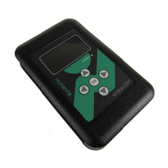
Noraxon U.S.A., Inc. myoMOTION Data Logger Component Inputs, Outputs and Indicators 1A Data Logger (Front) 1 Marker Button – When pressed, this button creates a marker in the record that can later be used in the analysis 2 LED Display – Guides the user through the setup and indicates the status of the data logger i.e. USB Ready, Measuring, etc. 3 Charge Indicator –Illuminates when the Data Logger is charging 4 Keypad – Used to navigate device setup and begin measurements 1B Data Logger (Side) 1. Power Switch – Toggles to turn the Data Logger OFF or ON 2. Sync Out – TTL (on‐off) compatible 3.5 mm stereo jack connection to other Noraxon devices used to send a sync pulse to other devices 3. Sync In – TTL (on‐off) compatible 3.5 mm stereo jack connection to other Noraxon devices used to accept a sync pulse generated by other devices ... -
Page 16: Component Interconnections
Noraxon U.S.A., Inc. myoMOTION Data Logger 1D Data Logger (Back) 1 Belt Clip – Used to secure the belt receiver to the user or the wall mount provided with the Data Logger 2 Serial Number – Unique 4 character serial number used to identify each data logger 2 MyoMOTION Sensor (front) 1 Serial Number – Unique 4 character serial number which identifies each sensor. 2 Axis Indicator – Indicates the orientation of the myoMOTION sensor. 3 Status – Sensor operational indicator flashes green. Flash rate is faster when measuring, slower when idle. 4 Charge – Indicator illuminates steady amber while sensor is charging. When the battery is fully charged the indication is off. Component Interconnections Step 1a For charging the data logger insert the mating (smaller) end of the USB cable (CBL17) into the USB connector on the side of the receiver. Insert the opposite end of the USB cable into the ... -
Page 17: Device Communication (Driver) Software Installation
No driver installation is needed. The myoMOTION Data Logger uses a G2 driver for communication over the USB port. Companion Software Installation The myoMOTION System is compatible with the Noraxon MR3 software program. To install MR3 follow the appropriate instructions given below: MR3 Installation 1. Insert the MR3 Software CD into the PC 2. -
Page 18: Section 7: Pre-Use Check-Out
When the pelvic sensor is used, an exact sensor positioning is not required; the accuracy of the sensor is not affected by a slight variance. The myoMOTION Sensors can be secured in place using Noraxon supplied double-sided adhesive tape, clips and/or elastic straps. Straps are recommended if dynamic movements are expected. -
Page 19: Section 8: Operating Instructions
The myoMOTION data logger (part #682) allows the user to travel with the moyMOTION sensors and portably record their data away from the PC. Recorded data can later be accessed with the use of a PC and Noraxon’s MR3 software. ... -
Page 20: Exceptional Functions/Situations (Error Messages)
Noraxon U.S.A., Inc. myoMOTION Data Logger Exceptional Functions/Situations (error messages) Error Message Meaning Too many sensors have been enabled or the sample rate is set too high. The data logger will Too many sensors support 16 sensors and 2 footswitches at 200Hz sample rate or 8 sensors at 200Hz... -
Page 21: Storage And Protecting Between Usages
Noraxon U.S.A., Inc. myoMOTION Data Logger Storage and Protecting Between Usages For extended storage or when travelling: Put the myoMOTION sensors into shutdown mode * Place all sensors into the sensor charging station Turn Data Logger off Position all components inside the system travelling case according to their prepared cavities * A special setting in the companion user software activates sensor shutdown mode. -
Page 22: Section 9: Accessories And Optional Modules Accessories
610/6 613 myoMOT TION Sensor 500‐IS S DTS Inso oles‐Pair As ne w accessories s may be ava ilable after th he time of pri nting, please e check Norax xon’s website at this s link for the latest offerin gs. http:/ //noraxon.com m/products P-6828 8 Rev A (Oct 201... -
Page 23: Section 10: Cleaning
Likewise, the myoMOTION Data Logger is not warranted against exposure to any of the conventional forms of sterilization. Users wishing to utilize this equipment in a sterile environment, such as an operating theater, should consult Noraxon for other options. P-6828 Rev A (Oct 2014) -
Page 24: Section 11: Maintenance
Companion Software Updates Perform a backup of the data folders to a separate drive as a precaution. Click on the Patch/Update link provided in the email or as given on the Noraxon website http://noraxon.com/support-resources Download the Patch/Update file. - Page 25 Noraxon U.S.A., Inc. myoMOTION Data Logger Maintaining an Optimal Wireless Connection As wireless devices are increasingly more commonplace, the radio traffic in any given location can change often abruptly. The myoMOTION system operates in the 2.4 GHz band which is shared by wireless networks and personal communication devices. The myoMOTION system can be set to operate at one of 8 different frequencies within the 2.4 GHz band as given in Appendix...
-
Page 26: Section 12: Trouble Shooting, Fault Diagnosis
(esp. at long distances) of-sight relationship between sensor and receiver Website Link to FAQ Answers to common questions can be found at Noraxon’s Frequently Asked Questions (FAQ) website page at this link: http://noraxon.com/support-resources/faq Other educational material is available at this link: http://www.noraxon.com/support-resources/resource-center/... -
Page 27: Radio Considerations
Noraxon U.S.A., Inc. myoMOTION Data Logger Radio Considerations The myoMOTION radio system operates in the 2400 MHz ISM (Industrial, Scientific and Medical) radio band reserved for use in most countries of the world. The radio transfers data digitally using a proprietary wireless sensor protocol. Other devices operating in this frequency band include computer networks, microwave ovens, cordless phone sets and other WiFi enabled devices. -
Page 28: Section 13: Service And Repair
If you are shipping from outside the USA please use UPS, FedEx, DHL, or EMS (US Postal Service) and not a freight-forwarder. Using a freight-forwarder incurs additional brokerage fees. If a package is shipped to Noraxon via a carrier other than the ones listed above, it may be refused. -
Page 29: Section 14: List Of Spare Parts And Consumables Consumable Items (Electrodes And Sensor Elements)
Norax xon U.S.A., In myoMOTIO N Data Logge ction 14 4: Spare e Parts a and Con nsumabl Cons sumable Ite ems Part Image Descr ription No. 610C Doubl le sided tape for attaching g myoMOTION N senso ors, 500 per pa ackage ... -
Page 30: Section 15: Taking Product Out Of Operation
Noraxon U.S.A., Inc. myoMOTION Data Logger Section 15: Taking Product out of Operation Disposal of Equipment and Batteries The myoMOTION Data Logger contains Li-Polymer batteries, which may be hazardous if disposed of incorrectly. Please check with the governing authorities in your location before disposing of the myoMOTION system and its contents. -
Page 31: Section 16: Specifications Of The Product
Noraxon U.S.A., Inc. myoMOTION Data Logger Section 16: Specifications of the Product Expected Useful Lifetime The myoMOTION Data Logger (#682) has a usable life of seven years. The myoMOTION Data Logger (#682) operates with a rechargeable Lithium Ion battery. The battery capacity will decline with ongoing use and require replacement after 500+ discharge/charge cycles to preserve the device’s rated 8 hours of operating time. -
Page 32: Section 17: Technical Information
Noraxon U.S.A., Inc. myoMOTION Data Logger Section 17: Technical Information Block Diagram Model 682 MyoMOTION Data Logger Coming soon… Theory of Operation The myoMOTION wireless system is based on a pre-certified transceiver module. This radio module operates in the 2.4 GHz bands with an output power level of 1 mW and is based on a Wireless USB product by Cypress Semiconductor. - Page 33 Noraxon U.S.A., Inc. myoMOTION Data Logger The myoMOTION system is intended for use in electromagnetic environment specified below. The customer or the user of the myoMOTION system should assure that it is used in such an environment. Immunity Test IEC 60601...
- Page 34 Noraxon U.S.A., Inc. myoMOTION Data Logger where P is the maximum output power rating of the transmitter in watts (W) according to the transmitter manufacturer and d is the recommended separation distance in metres (m). Field strengths from fixed RF transmitters,...
-
Page 35: Section 18: Appendices
Use a network sniffer program to determine which WiFi RF channels are being used in your area. InSSIDer” is a network sniffer with a graphical display that is available as a free download from the Noraxon website a, under the Drivers and Firmware section: http://www.noraxon.com/support-resources/ This network sniffer is compatible with Windows XP, Vista and 7 (32 and 64-bit). -
Page 36: Appendix B-Sensor Rf Channel Frequencies
Noraxon U.S.A., Inc. myoMOTION Data Logger Appendix B – Sensor RF Channel Frequencies The myoMOTION Sensors operate on a RF channel. The RF Channels (A-H) are assigned to the RF frequencies according to the table below. RF Channel Frequency (GHz) 2.400-2.409 2.415-2.424 2.427-2.436 2.439-2.448 2.451-2.460 2.463-2.472... -
Page 37: Appendix C-Radiation Exposure Information Regarding Use Of Dts Sensors
The myoMOTION sensors operate at radio frequencies known to effect older style pacemakers. Because the effects are not known at this time, Noraxon advises against using the myoMOTION system on anyone with an implanted pacemaker. -
Page 38: Appendix D-Radio Regulatory Statements
Noraxon U.S.A., Inc. myoMOTION Data Logger Appendix D – Radio Regulatory Statements FCC Statement This device complies with part 15 of the FCC rules. Operation is subject to the following two conditions: (1) This device may not cause harmful interference, and (2) this device must accept any interference received, including interference that may cause undesired operation.
Need help?
Do you have a question about the myoMOTION 682 and is the answer not in the manual?
Questions and answers