Table of Contents
Advertisement
Quick Links
Download this manual
See also:
User Manual
This Manual Covers Models:
G10-500
G20-250
G30-170
G40-125
G60-85
Manual Supplements
The full user manual is available on TDK-Lambda website or can be ordered, refer to User manual IA761-04-02_.
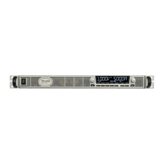
Programmable DC Power Supplies
5kW in 1U 0-600V/ 0-500A
Built in LAN, USB, RS-232 & RS-485 Interface
Optional Interface: IEEE488.2 (GPIB)
SAFETY & INSTALLATION MANUAL
G80-65
G100-50
G150-34
G300-17
G600-8.5
Series
GB10-500
GB20-250
GB30-170
GB40-125
GB60-85
GB80-65
GB100-50
GB150-34
GB300-17
GB600-8.5
IA761-04-01
Advertisement
Table of Contents

Related Manuals for TDK-Lambda G10-500


Summary of Contents for TDK-Lambda G10-500
- Page 1 G80-65 GB10-500 GB80-65 G20-250 G100-50 GB20-250 GB100-50 G30-170 G150-34 GB30-170 GB150-34 G40-125 G300-17 GB40-125 GB300-17 G60-85 G600-8.5 GB60-85 GB600-8.5 Manual Supplements The full user manual is available on TDK-Lambda website or can be ordered, refer to User manual IA761-04-02_. IA761-04-01...
- Page 2 This page intentionally left blank...
-
Page 3: Table Of Contents
TABLE OF CONTENTS WARRANTY ................................... 1 SAFETY & EMC APPROVALS ............................2 GENERAL SAFETY INSTRUCTIONS ........................... 4 ALLGEMEINE SICHERHEITSVORSCHRIFTEN ........................6 INSTRUCCIONES DE SEGURIDAD GENERALES ......................... 8 CONSIGNES GÉNÉRALES DE SÉCURITÉ .......................... 10 ISTRUZIONI GENERALI DI SICUREZZA ........................... 12 INSTRUÇÕES GERAIS DE SEGURANÇA .......................... 14 PRODUCT SAFETY INSTRUCTIONS .......................... - Page 4 3.6.2 AC Input Wire Connection ................35 3.7 Turn-On Checkout Procedure ................38 3.7.1 General ......................38 3.7.2 Prior to Operation ..................38 3.7.3 Constant Voltage Check ................38 3.7.4 Constant Current Check ................39 3.8 Connecting the Load ....................39 3.8.1 Load Wiring ....................
-
Page 5: Warranty
This product must be returned to an authorized TDK-Lambda service facility for repairs or other warranty service. For products returned to TDK-Lambda for warranty service, the buyer shall prepay shipping charges to TDK- Lambda and TDK-Lambda shall pay the shipping charges to return the product to the buyer. Refer section 3.9.5 for Repackaging for Shipment. -
Page 6: Safety & Emc Approvals
file at our EU representative TDK LAMBDA UK, located at Kingsley Avenue, Ilfracombe, Devon EX34 8ES, A “Declaration of Conformity” may be accessed via company web site www.uk.tdk-lambda.com/technical-data/ NOTE EMC tests are applicable only to output signals and communication ports up to 3m length and DC output ports up to 30m length. - Page 7 NOTE This equipment has been tested and found to comply with the limits for a Class A digital device, pursuant to Part 15 of the FCC rules. These limits are designed to provide reasonable protection against harmful interference when the equipment is operated in a commercial environment.
-
Page 8: General Safety Instructions
Failure to comply with the safety precautions or warnings in this document violates safety standards of design, manufacture and intended use of this equipment and may impair the built-in protections within. TDK-Lambda shall not be liable for user’s failure to comply with these requirements. SERVICING: These products are not customer serviceable. - Page 9 AC mains before making or changing any rear panel connection. Internal fuse Caution: Internal fuse protect the unit and must not be replaced by the user. In case of internal defect, the unit must be returned to TDK-Lambda Ltd. or one of their authorised agents. OTHER The ventilation openings on these products must not be impeded.
-
Page 10: Allgemeine Sicherheitsvorschriften
Benutzer entstehen können. WARTUNG: Diese Produkte können nicht durch den Kunden gewartet werden. Ersatzteilaustausch und Modifikationen dürfen nur durch von TDK-Lambda zugelassenes Personal durchgeführt werden. Für Reparaturen oder Modifikationen muss das Gerät an einen Vertriebspartner von TDK- Lambda geschickt werden. KRITISCHE KOMPONENTEN: Diese Produkte sind nicht für die Verwendung als kritische Komponenten in nuklearen Kontrollsystemen,... - Page 11 GEFAHR VON ELEKTRISCHEM SCHLAG Hochspannungswarnung: Innerhalb des Netzteiles gibt es gefährliche Spannungen. Um Personenschäden zu vermeiden, muss vor dem Kontakt mit dem Gerät immer die Stromversorgung unterbrochen, die Stromkreise entladen und externe Spannungsquellen entfernt werden. Schutzklasse I Warnung: Das Gerät ist ein Produkt der Schutzklasse 1. Zur Vermeidung gefährlicher Energieinhalte und Spannungen, ist das Gerät an eine zuverlässige Schutzerde anzuschließen und durch Fachleute zu installieren.
-
Page 12: Instrucciones De Seguridad Generales
TDK-Lambda no asumirá responsabilidad alguna si el usuario no cumple estos requisitos. - Page 13 CA antes de realizar o cambiar cualquier conexión del panel posterior. Precaución sobre el fusible interno: el fusible interno protege la unidad y no debe ser sustituido por el usuario. En caso de defecto interno, la unidad deberá enviarse a TDK-Lambda Ltd. o a alguno de sus agentes autorizados.
-
Page 14: Consignes Générales De Sécurité
été conçus pour être utilisés comme composants critiques de systèmes de commande nucléaire, de survie ou d’équipements utilisés dans des environnements dangereux, sans l'autorisation écrite expresse du directeur général de TDK-Lambda Ltd. UTILISATION DU PRODUIT: ces produits ont été conçus pour être utilisés de manière autonome, conformément aux limites indiquées dans le Manuel y afférent. - Page 15 Précaution relative au coupe-circuit interne: un fusible interne protège l'appareil et ne doit pas être remplacé par l'utilisateur. En cas de défaut interne, renvoyez l'appareil à TDK-Lambda Ltd. ou à l'un de ses agents agréés. AUTRE Les ouïes d'aération de ces produits doivent être libres de toute entrave.
-
Page 16: Istruzioni Generali Di Sicurezza
Questi prodotti non possono essere sottoposti a manutenzione da parte del cliente. Qualunque sostituzione o modifica dei componenti deve essere affidata esclusivamente al personale di manutenzione di TDK-Lambda. Per eventuali riparazioni o modifiche, il prodotto deve essere inviato al centro assistenza di TDK-Lambda. - Page 17 CA prima di eseguire o modificare qualsiasi collegamento sul pannello posteriore. Precauzione - fusibile interno: Il fusibile interno protegge l’unità e non deve essere sostituito dall’utente. Nell’eventualità di un difetto interno, l’unità deve essere inviata a TDK-Lambda Ltd. o a un suo agente autorizzato. ALTRO Le aperture di ventilazione su questi prodotti non devono essere ostruite.
-
Page 18: Instruções Gerais De Segurança
A não observância dos avisos e precauções de segurança constantes neste documento viola os padrões de segurança da concepção, fabrico e utilização pretendida deste equipamento, podendo danificar as protecções integradas no seu interior. A TDK-Lambda não poderá ser responsabilizada pelo não cumprimento destes requisitos por parte do utilizador. - Page 19 Cuidados com o fusível interno: O fusível interno protege a unidade e não deve ser substituído pelo utilizador. Em caso de defeito interno, a unidade deve ser devolvida à TDK-Lambda Ltd. ou a um dos seus agentes autorizados.
-
Page 20: Product Safety Instructions
Failure to comply with the safety precautions or warnings in this document violates safety standards of design, manufacture and intended use of this equipment and may impair the built-in protections within. TDK-Lambda shall not be liable for user’s failure to comply with these requirements. - Page 21 LIVE CIRCUITS Operating personnel must not remove the instrument cover. No internal adjustment or component replacement is allowed by non-TDK-Lambda qualified service personnel. Never replace components with a power cable connected. To avoid injuries, always disconnect power, discharge circuits, and remove external voltage sources before touching components.
- Page 22 PARTS SUBSTITUTIONS & MODIFICATIONS Parts substitutions and modifications are allowed by authorized TDK-Lambda Ltd. service personnel only. For repairs or modifications, the instrument must be returned to TDK-Lambda Ltd. service facility. AUSWECHSELN UND VERÄNDERUNG VON BAUTEILEN Das Auswechseln sowie die Abänderung von Teilen darf nur von autorisierten TDK-Lambda Ltd.
-
Page 23: Fuse Rating
Fuses must be changed by authorized TDK-Lambda Ltd. service personnel only. For continued protection against risk of fire, replace only with the same type and rating of the fuse. - Page 24 SICHERUNGSWERTE Im Gerät befinden sich keine Sicherungen, die durch den Anwender ersetzt werden können. Die internen Netzsicherungen dienen als Fehlerschutz. Wenn eine solche Sicherung ausgelöst hatte, ist dies ein eindeutiger Hinweis, dass das Gerät gewartet werden muss. Ein Sicherungstausch sollte nur von qualifiziertem technischen Personal ausgewechselt werden.
- Page 25 GERÄUSCHPEGEL Maschinenlärm - Verordnung - 3. GPSGV, der höchste Schalldruckpegel beträgt weniger als 70 dB(A) gemäss EN ISO7779. SYMBOLS/ ZEICHEN Caution, risk of danger. Instruction manual symbol. The instrument will be marked with this symbol when it is necessary for the user to refer to the Safety & Installation or Instruction manual. Achtung Gefahr.
-
Page 26: Chapter 1: General Information
CHAPTER 1: GENERAL INFORMATION User Manual Content This safety & installation manual contains the operating instructions, installation instructions of the ™ 5000W power supply series. The instructions refer to the standard & Blank power supplies, including the built-in USB, LAN and RS232/485 serial communication. For information related to operation with the optional GPIB communication interface, refer to User manual (Chapter 8) in the CD-ROM. -
Page 27: Analog Voltage Programming And Monitoring
• Under-Voltage limit setting and read back. • Power-supply start up mode (last setting or safe mode). 1.2.4 Analog Voltage Programming and Monitoring Analog inputs and outputs are provided at the rear panel for analog control of the power supply. The output voltage and the current limit can be programmed by analog voltage or by resistor, and can be monitored by analog voltage. -
Page 28: Misc. Hardware
1.3.1.5 Misc. Hardware • DB-26 Connector P/N: 10090769-P264ALF (FCI) • DB-15 Backshell P/N: 86303638BLF (FCI) • CD-ROM • SEMS Screw M3X6 Fe Ni, 2 Pcs. • Flat head screw M3X8 Fe Ni, 2 Pcs. 1.3.1.6 Bus bars Screws kits 10V~40V Models •... -
Page 29: Chapter 2: Front/Rear Panel Controls And Connectors
CHAPTER 2: FRONT/REAR PANEL CONTROLS AND CONNECTORS Introduction ™ Power Supply series has a full set of controls, indicators (in the standard units) and connectors that allow the user to set up and operate the unit. Before starting to operate the unit, please read the following sections for an explanation of the functions, controls and connector terminals. - Page 30 Control/Indicator Description Section SYST / Lock Front Panel Activates System menu. System menu provides output sensing button / Indicator point selection (Local / Remote sense), Interlock function control, Enable function control, Power Supply OK signal control, SAVE/RECALL Power Supply configuration, Programmable Signals control, Preload function control, Display brightness &...
-
Page 31: Rear Panel Connectors
Rear Panel Connectors Refer to Figure 2-2 and Table 2-2 for description of the Rear Panel connectors. Figure 2-2: Rear panel connectors Connection Description AC Input Connector Connector type: Phoenix contact P/N: PC 5/ 4-G-7,62 Ground Stud Functional Ground connection M4x8 Stud DC output bus-bar / Bus-bars for 10V to 100V models. - Page 32 CAUTION To prevent ground loops and to maintain the isolation of the power supply when programming from J1, use an ungrounded programming source. VORSICHT Um Erdschleifen zu verhindern und die Isolierung auf dem Netzgerät aufrecht zu erhalten, wenn Sie von J1 programmieren, müssen Sie eine ungeerdete Programmierquelle benutzen. WARNING There is a potential shock hazard at the output when using a power supply with an output greater than 60VDC.
-
Page 33: Chapter 3: Installation
CHAPTER 3: INSTALLATION CAUTION Observe all torque guidelines within this manual. Over torque may damage unit or accessories. Such damage is not covered under manufacturer’s warranty. VORSICHT Beachten Sie alle Drehmoment-Richtlinien in diesem Handbuch. Wird ein zu großes Drehmoment eingestellt bzw.verwendet, können dadurch das Gerät oder die Zubehörteile beschädigt werden. -
Page 34: Initial Inspection
Keep all packing material until the inspection has been completed. If damage is detected, file a claim with carrier immediately and notify the TDK-Lambda sales or service facility nearest you. Rack Mounting ™... -
Page 35: Rack Mount Slides (Optional)
3.4.2 Rack Mount Slides (Optional) Use rack mount slides: General Devices Catalog Number: C-300-S-116. Part/Drawing Number: CC3001-00-0160 or equivalent to install the unit in a standard 19" equipment rack. Refer to Figure 3-1 for slides assembly instructions. Use three #10-32x0.38"(max.) screws at each side. To prevent internal damage, use the specified screw length only. -
Page 36: Ac Input Power Connection
AC Input Power Connection This Power supply shall be connected to the AC source via protective device (Circuit breaker, fuses…etc.), rated for 30A. WARNING There is a potential electrical shock hazard when using a power supply without input protection. Do not connect power supply to AC supply line without input protection properly assembled. - Page 37 Stromschlags zu verhindern, trennen Sie das Netzkabel vom Versorgungsnetz und warten dann zwei Minuten, bevor Sie die Schutzabdeckung abnehmen. Nur qualifizierte Servicekräfte von TDK-Lambda dürfen die Gehäuse-Abdeckung abnehmen. CAUTION AC Input Wires No Conductor Pretreatment: All kinds of copper conductors can be clamped without pretreatment (Solid, Flexible, with ferrule, with/without plastic sleeve).
-
Page 38: Ac Input Connector
CAUTION The power supply ON/OFF switch is not the main "disconnect device" and does not completely disconnect all the circuits from the AC source. An appropriately rated "disconnect device" such as circuit breaker, type B plug on power cord, etc., shall be provided in the final installation. -
Page 39: Ac Input Wire Connection
3.6.2 AC Input Wire Connection 1. Strip the outside insulation of the AC cable approx. 10cm. Trim the wires so that the ground wire is 10mm longer than the other wires. Strip 10mm at the end of each of the wires. Insert the Cable gland into the Strain relief bracket Assembly as shown in Figure 3-2. - Page 40 Tighten the screws, tightening torque: 4.5-5.3 Lbf-inch. (0.5-0.6Nm). Figure 3-4: AC Wires Fixed to the AC Connector After fixing the wires, close by manual force the cable gland conic entry part until the AC cable will be well tightened. Beware not to apply excessive force. Now the cable is securely fastened inside the strain relief assembly.
- Page 41 Figure 3-6: Strain Relief Assembled to the Power Supply Rear Panel...
-
Page 42: Turn-On Checkout Procedure
Turn-On Checkout Procedure WARNING There is a potential electrical shock hazard when using a power supply without output protection. Do not turn ON power without output protection properly assembled. Turn OFF power supply or disconnect power supply from AC mains before making or changing any rear panel connection. -
Page 43: Constant Current Check
Compare the DVM reading with the front panel Voltage display to verify the accuracy of the Voltage display. Ensure that the front panel CV indication on the LCD screen is active. Turn off the front panel Power switch. 3.7.4 Constant Current Check 1. -
Page 44: Load Wiring
WARNUNG Bei Einsatz eines Netzgeräts mit einer Ausgangsspannung von über 60 VDC besteht das Risiko eines Stromschlags. Schalten Sie die AC-Eingangsspannung immer AUS, bevor Sie irgendwelche Anschlüsse an der Geräterückseite vornehmen oder verändern. Stellen Sie sicher, dass die Schutzabdeckung des Ausgangssteckers ordnungsgemäß angebracht ist, wenn Ausgangsspannungen von mehr als 60 VDC auftreten können. -
Page 45: Wire Termination
Output current Recommended wires Recommended Recommended lugs/Connector (mm²) wires (AWG) 2 AWG 2 AWG Panduit LCMA25-8-C Or equivalent 125A "0" AWG "0" AWG Panduit LCMD50-10CD-X Or equivalent 170A 3/0 = 000 3/0 = 000 Panduit LCMD70-10CD-X Or equivalent 250A 4/0 = 0000 4/0 = 0000 Panduit LCMD95-10CD-X Or equivalent... -
Page 46: Inductive Loads
3.8.5 Inductive Loads Inductive loads can produce voltage spikes that may be harmful to the power supply. A diode should be connected across the output. The diode voltage and current rating should be greater than the power supply maximum output voltage and current rating. Connect the cathode to the positive output and the anode to the negative output of the power supply. - Page 47 1. Prepare suitable wires and lugs according to the recommendations in Table 3-2. Assemble and solder the lugs properly. 10V ~ 40V Models CAUTION For high current outputs, it is very important to make the output connections properly, and follow the instructions.
- Page 48 For 10V model only: 1. Fix the wires to the Bus bars as shown in Figure 3-8. Close the output protection assembly. In this model the plastic protectors will not be assembled. M10 Hex. Nut Tightening torque: 220 ~ 265 lbf-in. 24.9~ 29.9 Nm Flat washer close to Bus...
- Page 49 Flat washer close to Bus bars, then spring washer M10 Hex. Nut Tightening torque: 220 ~ 265 lbf-in. Screws 24.9~ 29.9 Nm Flat Washers One part of plastic protector assembled Figure 3-10: 20V ~ 40V Wires Assembly Assemble the Bus bars protection assembly to the rear panel of the power supply, by using 2 M3X6 Sems screws from the accessories kit, as shown in Figure 3-11.
- Page 50 For 60V ~ 100V models: The recommended wires according to Table 3-2 can be inserted through the output protection assembly. No need to open the output protection assembly. Refer to Figure 3-12: Flat washer close to Bus bars, then spring washer M8 Hex.
- Page 51 CAUTION Output Wires No Conductor Pretreatment: All kinds of copper conductors can be clamped without pretreatment (Solid, Flexible, with ferrule, with/without plastic sleeve). It is forbidden to solder the conductors. The solder tin yields and fractures under high pressure. The result is an increased contact resistance and an excessive temperature rise. In addition, corrosion caused by pickling or fluxes has been observed on soldered conductor ends.
- Page 52 Mating CONNECTOR (IPC 5/ 4-STF-7,62, PHOENIX CONTACT) Figure 3-13: Load Wires Connection to the Output Plug Fix the Output protection assembly to the rear panel of the power supply and tighten the screws as shown in Figure 3-14. Tightening torque: 4.7 ~ 5.7 Lb-inch (0.53 ~ 0.64 Nm). Figure 3-14: Output Connector Protection Assembly...
-
Page 53: Grounding Outputs
3.8.7 Grounding Outputs Either the positive or negative output terminals can be grounded. To avoid noise problems caused by common-mode current flowing from the load to ground, it is recommended to ground the output terminal as close as possible to the power supply chassis ground. Always use two wires to connect the load to the power supply regardless of how the system is grounded. -
Page 54: Local And Remote Sensing
Local and Remote Sensing The rear panel J8 sense connector may be used to configure the power supply for remote sensing of the output voltage. Refer to Figure 2-2 for sense connector location. 3.9.1 Sense Wiring WARNING There is a potential shock hazard at the sense connector when using a power supply with an output voltage greater than 60VDC. -
Page 55: J8 Sense Connector Technical Information
3.9.5 Repackaging for Shipment To ensure safe transportation of the instrument, contact the TDK-Lambda sales or service facility near you for Return Authorization and shipping information. Please attach a tag to the power supply describing the problem and specifying the owner, model number and serial number of the power supply. - Page 56 NOTES ________________________________________________ ________________________________________________ ________________________________________________ ________________________________________________ ________________________________________________ ________________________________________________ ________________________________________________ ________________________________________________ ________________________________________________ ________________________________________________ ________________________________________________ ________________________________________________ ________________________________________________ ________________________________________________ ________________________________________________ ________________________________________________ ________________________________________________ ________________________________________________ ________________________________________________ ________________________________________________ ________________________________________________ ________________________________________________ ________________________________________________ ________________________________________________ ________________________________________________ ________________________________________________ ________________________________________________...
Need help?
Do you have a question about the G10-500 and is the answer not in the manual?
Questions and answers