
Subscribe to Our Youtube Channel
Related Manuals for Enfora Enabler EDG0208


Summary of Contents for Enfora Enabler EDG0208
- Page 1 Integration Guide: EDG0208IG001 Enfora Enabler IIE Quad-Band GSM/GPRS/EGPRS Modem Integration Guide Version 1.00...
- Page 2 All specifications are subject to change without notice and do not represent a commitment on the part of Enfora, Inc. Enfora, Inc. will not be responsible for any loss or damages incurred related to the use of information contained in this document.
-
Page 3: Table Of Contents
Integration Guide Draft Table of Contents SAFETY PRECAUTIONS..........1 ........................1 MPORTANT AFETY NFORMATION REGULATORY COMPLIANCE FCC ......1 INTEGRATION CONSIDERATIONS AND INSTALLATION REQUIREMENTS ........1 DISCLAIMER ..............2 MANUAL OVERVIEW ............4 ... - Page 4 10.2 GSM/SMS E ............................. 46 XAMPLES 10.2.1 Initialize the Enfora Enabler EDG0208 Module to Send and Receive SMS Text Messages ....46 10.2.2 Managing SMS Messages ........................46 10.2.3 Data Call Configuration ......................... 46 ...
- Page 5 Integration Guide Draft 11.2.2 Hardware ..............................49 11.2.3 Software ..............................49 11.2.4 Other Considerations ..........................50 11.3 APPENDIX B - R .................... 51 EGULATIONS AND OMPLIANCE 11.3.1 GCF/PTCRB Approval (Formerly FTA) ....................51 ...
-
Page 6: Safety Precautions
Save this manual: it contains important safety information and operating instructions. Do not expose the Enfora Enabler EDG0208 product to open flames. Ensure that liquids do not spill into the devices. ... -
Page 7: Disclaimer
PTCRB, R&TTE, IMEI and other applicable codes that are in effect at the time of publication. Enfora disclaims all responsibility for any act or omissions, or for breach of law, code or regulation, including local or state codes, performed by a third party. - Page 8 Integration Guide Draft Enfora shall not be liable for consequential or incidental damages, injury to any person or property, anticipated or lost profits, loss of time, or other losses incurred by Customer or any third party in connection with the installation of the Products or Customer's failure to comply with the information and instructions contained herein.
-
Page 9: Manual Overview
Draft 3.0 Manual Overview This document describes the hardware interface of the Enabler EDG0208 GSM/GPRS OEM Modem. The purpose of this document is to define the electrical, mechanical and software interfaces while providing detailed technical information in order to streamline the process of hardware and system integration. -
Page 10: Gsm Device Specifications: Www.3Gpp.org
Integration Guide Draft 3.1.2 GSM Device Specifications: www.3gpp.org 3GPP TS 51010-1 (850, 900,1800,1900 MHz devices) 3.1.3 Federal Communications Commission (FCC) Internet: http://www.fcc.gov/ FCC Rules, Part 24 47 CFR Subpart E--Broadband PCS 47 CFR § 24.52, sections 1.1307(b), 2.1091, and 2.1093 ... -
Page 11: Introduction
The Enfora Enabler EDG0208 module is available as a quad band version. The Enfora Enabler EDG0208 module is designed to be a drop in replacement for the Enabler II E EDG0108 module. It’s physical size, electrical specifications and physical connectors are identical to the EDG0108 for a seamless transition. -
Page 12: Providing Multi-Band Operation
The GSM900 / DCS1800 MHz bands are available for use in Europe and the rest of the world. 4.4 Wireless Data Application Possibilities A variety of applications can use the Enfora Enabler EDG0208 module for transmitting and receiving data and voice, such as: ... -
Page 13: General Design Guidelines For Utilizing Enfora Gsm Modules
Integration Guide Draft 4.5 General design guidelines for utilizing Enfora GSM modules The following guidelines are provided in an effort to allow Enabler IIE module users to successfully implement their PCB layout to obtain the best performance. This includes the lowest possible EMI emissions, maximum thermal conduction, mechanical integrity, and voice quality. -
Page 14: Advanced Tips For An Rf Friendly Layout
Integration Guide Draft 4.6 Advanced tips for an RF friendly layout Ground Plane To ensure the lowest possible EMI emissions and maximum thermal conductivity, it is recommended that all metal tabs on the GSM module shield must be soldered down onto a continuous ground plane that runs under the entire module. -
Page 15: Figure 2 - Example Of A Poor Rf Thermal Relief
Integration Guide Draft Thermal Relief Because the ground plane acts as a large heat sink, it can affect the solderability of components. A common method to reduce this effect is to use thermal relief around the pad in question. However, great care must be taken when using thermal relief for high current or high frequency applications For example, a large thermal relief like the one shown in Figure 2 can serve the purpose for general applications such as low current, low speed data lines, DC connections and audio... -
Page 16: Figure 3 - Example Of A Good Rf Thermal Relief
Integration Guide Draft GOOD RF thermal relief Figure 3 - Example of a GOOD RF Thermal Relief Antenna and RF Signal Trace The PCB trace that feeds the RF output port must be designed for a 50 ohm characteristic impedance, coplanar, or routed into internal layers to keep the top layer continuous around and underneath the Enabler module. -
Page 17: Figure 4 - Example Of Vbat Voltage Droop
Integration Guide Draft Vbat Input The Enabler Vbat input can have a relative high current draw that can fluctuate rapidly, especially when transmitting at max power and burst mode. The Vbat interface must be designed to provide the required instantaneous voltage and current with minimal voltage droop. -
Page 18: Audio Reference Design
Integration Guide Draft Vbat trace Figure 5 - Example of GOOD Vbat layout 4.7 Audio Reference Design The audio quality is very dependent on the circuit design and layout. As an aid to obtaining good audio quality, a reference design has been included below. It has been proven to provide good performance on the SDK module. -
Page 19: Figure 6 - Audio Reference Design Schematic
Integration Guide Draft Figure 6 - Audio Reference Design Schematic Audio Layout Layout plots for the audio section of the SDK are available upon request. EDG0208IG001 Page 14 Rev. 1.03 –4/19/07... -
Page 20: Technical Specifications
5.0 Technical Specifications 5.1 Enabler EDG0208 Module Block Diagram Analog Audio Baseband/ Antenna Analog BB RX Intfc. Power Interface Intfc. Mgmt GPIO Digital SRAM/ Baseband/ Flash Memory Ser. Intfc. Figure 7 Enabler EDG0208 Module Block Diagram EDG0208IG001 Page 15 Rev. 1.03 –4/19/07... -
Page 21: Detailed Product Specifications
Integration Guide Draft 5.2 Detailed Product Specifications Physical Dimensions and Weight Size (L x W x H) 46.3 mm x 30.2 mm x 3.1 mm Weight 8.2 grams. Climatic: Operational Operating temperature -20°C to +60°C Relative humidity 5 - 95% Solar radiation Not Applicable Air pressure (altitude) -
Page 22: Operating Power
Integration Guide Draft Electromagnetic Emissions FCC Part 24 / Part 15 Class \ B Radiated spurious TS 51.010-1 Section 12.2 EN 55022 Class B Electromagnetic Immunity (per ETSI ETS 300 342-1) Radio Frequency (RF) Electromagnetic Field 3 V/m 800 – 1000 MHz; 1 kHz 80% EN 61000-4-3 Contact discharge to coupling planes: ±2 kV, ±4 kV Electrostatic discharge (ESD) -
Page 23: Egprs Operating Power
Integration Guide Draft 5.3.3 EGPRS Operating Power EGPRS Operation Input Current Band Mode Nom/Avg High/Peak Units 3 RX/1TX, Full Power 1038 2 RX/2TX, Full Power 1078 1900 1 RX/1TX, Full Power 3 RX/1TX, Full Power 1078 2 RX/2TX, Full Power 1210 1800 1 RX/1TX, Full Power... -
Page 24: Mechanical
Integration Guide Draft 6.0 Mechanical Figure 8 – Front of EDG0208-00 & -01 Figure 9 – Back of EDG0208-00 EDG0208IG001 Page 19 Rev. 1.03 –4/19/07... -
Page 25: Figure 10 - I/O, Rf Connector, & Mounting Tabs
Integration Guide Draft Figure 10 - I/O, RF Connector, & Mounting Tabs EDG0208IG001 Page 20 Rev. 1.03 –4/19/07... -
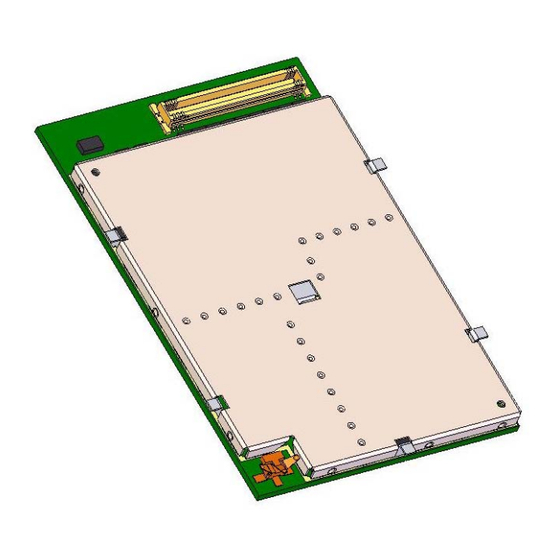
Page 26: Figure 11 - Back Of Edg0208-01
Integration Guide Draft Figure 11 – Back of EDG0208-01 EDG0208IG001 Page 21 Rev. 1.03 –4/19/07... -
Page 27: Figure 12 - Edg0208-01 Side View (Mm)
Integration Guide Draft Figure 12 - EDG0208-01 Side View (mm) EDG0208IG001 Page 22 Rev. 1.03 –4/19/07... -
Page 28: Figure 13 - Back Of Edg0208-01
Integration Guide Draft Figure 13 - Back of EDG0208-01 EDG0208IG001 Page 23 Rev. 1.03 –4/19/07... -
Page 29: Figure 14 - Front Of Edg0208-02
Integration Guide Draft Figure 14 – Front of EDG0208-02 EDG0208IG001 Page 24 Rev. 1.03 –4/19/07... -
Page 30: Enabler Ii-E Mounting To Host Board (Reference)
Integration Guide Draft 6.1 Enabler II-E Mounting to Host Board (Reference) The Enabler II-E provides mounting tabs that can be soldered to a PCB. These tabs provide circuit grounding for the module and their use is recommended. Figure 15 – Enabler II-E Mounting EDG0208IG001 Page 25 Rev. -
Page 31: I/O Connector
Integration Guide Draft 6.2 I/O Connector 60-Pin I/O Connector, SMT, Dual Row, 0.5 mm (.020") Pitch The 60-pin connector on the modem is a Molex 53729-0608. The 60-pin connector required on the host board is a Molex 52974-0604 (or –0608). The mated height of the two connectors is 2.00 mm. -
Page 32: I/O Signal Connector On The Enfora Enabler Edg0208 Module
6.4 I/O Signal Connector on the Enfora Enabler EDG0208 Module The Enfora Enabler EDG0208 module communicates with the carrier board of the application via the 60-pin I/O signal connector. The following table describes the pin assignments for the connector, sorted by pin number. -
Page 33: Circuit Protection
6.5 Circuit Protection Other than the basic low level ESD protection within the module’s integrated circuits (typically 2000 V), the Enabler EDG0208 does not have any protection against ESD events or other excursions that exceed the specified operating parameters. The only exception is that the remote SIM lines on the main I/O connector do have additional ESD protection that should handle standard human-model contact ESD events. -
Page 34: Control Connector Signal Descriptions And Functions
6.7 Control Connector Signal Descriptions and Functions 6.7.1 Input Power The Enfora Enabler EDG0208 module uses a single voltage source of VCC=+3.3V to 4.5V. (exact values of the uplink currents are shown in Tables 5.3.1 GSM Operating Power and 0 GSM Operation... -
Page 35: Ring Indicate
6.7.2 Ring Indicate The Enabler EDG0208 module is capable of using the Ring line to discern the type of incoming call. The indicator can be monitored via a hardware line available on the 60 pin I/O signal connector. The Ring Indicator pin is #49. -
Page 36: Radio Power/Reset (Pin 22)
Integration Guide Draft 6.7.3 Radio Power/Reset (Pin 22) A pulse on this Active-High input resets/restarts the module. This input has a “weak pull-down” resistor internal to the module and can be left open-circuit or grounded if it is not going to be used. To initiate a reset, provide a high-pulse of at least 50 ms duration. -
Page 37: Serial Interface (9 Pin I/F) (See Table In Section 6.4.1 I/O Connector Pin Assignments)
Output Voltage – High Rated Output Current The Enabler EDG0208 is designed to be used like a DCE device. RxData is the serial data from the modem to the host. TxData is the serial data from the host to the modem. -
Page 38: Analog-To-Digital Input
Resistive Load At Internal Speaker (+) or (-) Common Mode Maximum Capacitive Load Amplifier Gain Enfora recommends an external audio amplifier for loads of less than 16 or if volume is inadequate. 6.7.10 Headset Microphone Input Parameter Parameter/Conditions UNIT Inputs 3 dBm0 (Max. -
Page 39: Headset Speaker Output
Maximum Resistive Load Amplifier Gain HighZ Amplifier State in Power Down The headset speaker output is a single ended output. Enfora recommends an external audio amplifier for loads of less than 32 or if volume is inadequate. 6.7.12 Audio Design Note Speaker and microphone PCB traces should be run in pairs and buried between two ground planes for best results. -
Page 40: Figure 18 Audio Reference
Integration Guide Draft Figure 18 Audio Reference (Please note that this schematic can be zoomed to read the detail) EDG0208IG001 Page 35 Rev. 1.03 –4/19/07... -
Page 41: Transmit Active Output (Pin-37)
Note: The SIM is not provided with the Enfora Enabler EDG0208 module. The SIM must be obtained from the GSM service provider and must be provisioned by the operator for data and/or voice. Always take care to protect the SIM: the GSM terminal will not operate without the SIM installed. -
Page 42: Remote Sim Component Information
8 kV Contact Discharge 6.8.3 Remote SIM Component Information A SIM carrier compatible for use on the Enabler EDG0208 is a JAE Plug-In SIM Card carrier with hinge; JAE Plug-in SIM Card with hinge cover SF7 Series JAE part number SF7W006S1BE1000... -
Page 43: Modes Of Operation
The Enfora Enabler EDG0208 module has full voice capabilities, provided the necessary connections have been made for the speaker and microphone pins on the 60-pin I/O connector. The Enfora Enabler-IIE AT Command Set Reference - EDG0208AT001 has the entire list of commands that can be used to control the voice functionality. -
Page 44: Sms: Short Message Services
Integration Guide Draft 7.4 SMS: Short Message Services Short Message Services (SMS) is a feature-rich GSM service. The Enfora Enabler EDG0208 module can perform the following tasks: Sending and receiving binary messages of up to 160 characters (7-bit characters) ... -
Page 45: Sim Operation
Mobile-terminated (MT): allows receiving a service request (such as, receiving a phone call or an SMS) It is imperative for the Enfora Enabler EDG0208 module that the SIM be configured for the optional services that are required for the application. -
Page 46: Selecting The Modes Of Operation
Multi-slot 10 Class of Service. 8.5 Selecting the Modes of Operation When provisioning the SIM for the Enfora Enabler EDG0208 module, enable the following modes of operation: Voice calls: configure the SIM for both MO and MT service (to send and receive);... -
Page 47: Software Interface
Enfora Enabler EDG0208 module in Command mode but does not terminate the circuit-switched data call.) The AT command driver of the Enfora Enabler EDG0208 module never exits the Command state, that is, it never enters the “On-line” mode. ... -
Page 48: Setup And Initialization
The following provides an example for setting up a Windows HyperTerminal session that can be used to experiment with various configurations on the Enabler EDG0208 for controlling computer: 1. Select the connection interface, Direct to Com 1 (or whatever port is the serial port). -
Page 49: Initialization (At Command Interface)
"mobile-terminated call" or "incoming call." In the following examples, “Entry” refers to the application. The following convention describes the direction of the data exchange: The data exchange from the customer application to the Enfora Enabler EDG0208 module is designated as: Entry ... -
Page 50: Initial Response To The At Command
Command valid: module is ready Response The Enfora Enabler EDG0208 module must be in AT Command mode (please refer to section 10.3 GPRS Packet Examples for packet mode initialization and setup) when any command is entered (with the exception of the online escape sequence). Commands entered when the module is in On-line mode are treated as data, and are transmitted as such to the receiving module. -
Page 51: Querying The Status Of The Enfora Enabler Edg0208 Module
10.3.2 Windows PPP Setup The Enabler EDG0208 module can be used in a Windows operating system environment as a standard serial modem device. The required setup and configuration process is contained in Enfora Application Notes GSM0000AN001 - Enabler-G PPP Configuration for Windows 98 and GSM0000AN002 - Enabler- G PPP Configuration for Windows 2000. -
Page 52: Integration And Testing
Draft 11.0 Integration and Testing The Enfora Enabler EDG0208 module has been designed to minimize the amount of time required for integration and testing the application. By being fully certified by the appropriate bodies, the Enfora Enabler EDG0208 module provides seamless integration into the GSM network. - Page 53 Integration Guide Draft Testing the following parameters verifies the RF parameters that may be affected by such things as RF path loss, power supply noise, and external interference. Functionality Parameters to be Tested Frequency Error Transmitter Phase Error PA Ramp Modulation Spectrum RF Power Steps Timing Advance...
-
Page 54: Appendix A - Limited Warranty
11.2.1 Scope Enfora warrants to the original purchaser of the product that, for a period of one (1) year from the date of product purchase, the product hardware, when used in conjunction with any associated software (including any firmware and applications) supplied by Enfora, will be free from defects in material or workmanship under normal operation. -
Page 55: Other Considerations
Draft Exceptions and Disclaimers Enfora shall have no obligation under this limited warranty for (a) normal wear and tear, (b) the cost of procurement of substitute products or (c) any defect that is (i) discovered by purchaser during the warranty... -
Page 56: Appendix B - Regulations And Compliance
Unintentional emission: FCC Rules, Part 15 Although the Enfora Enabler IIE module has been authorized by the FCC and listed as a component by an NRTL, products and applications that incorporate the Enfora Enabler IIE module will require final verification of EM emission and product safety approval. -
Page 57: Unintentional Radiators, Part 15
Equipment designated as Class A is intended for use in a commercial, industrial or business environment. The Enfora Enabler IIE module has been tested and found to comply with the limits for a Class A digital device and can be integrated into equipment or applications intended for use in commercial, industrial or business environments. -
Page 58: Instructions To The Original Equipment Manufacturer (Oem)
Internet at the OET web site: http://www.fcc.gov/oet The Enfora Enabler IIE products are GSM radio transceivers, which operate under the authority of 47 CFR Part 24, Subpart E and Part 22 of the FCC Rules and Regulations. When installed and operated in accordance with the instructions provided in this manual, these devices comply with current FCC regulations regarding human exposure to radio frequency radiation. - Page 59 Integration Guide Draft Note: Additional care must be taken by the installer and/or user of the Enfora Enabler IIE products to ensure proper antenna selection and installation. Adherence to the above conditions is necessary to comply with FCC requirements for safe operation regarding exposure to RF radiation.
-
Page 60: Oem Responsibilities For All Products Containing The Enabler Iie Module
In addition to any other regulatory requirements, OEMs and integrators must include or provide the following information, instructions, warnings and labels with any device or product into which the Enfora Enabler IIE GSM1900 GSM transceiver has been incorporated: Information Description... -
Page 61: Specific Oem Responsibilities For Portable Products And Applications
In most other countries that have not been listed above there are similar rules and regulations that must be met for importing the Enfora Enabler IIE module. Each may require a different mark of approval (for example, the CB Scheme) as an acceptance requirement. For each of these cases the country should identified, and the appropriate steps should be taken to meet the requirements set forth in the intended market. -
Page 62: Appendix C - Glossary And Acronyms
Application Programming Interface. Refers to the Application which sends or receives commands/responses from the App Application Enfora Enabler IIE Module Commands issued by intelligent device to a modem to perform functions, such as to AT Command Set initiate call, to answer call, or to transmit data. - Page 63 Integration Guide Draft records for billing, and supervises system operations. Mobile Switching Center Delivers a constantly low error rate but with a non-guaranteed throughput or delay. Non-Transparent Mode The Non-Transparent service provides a performance that is closest to using a modem over a fixed PSTN line.
-
Page 64: Appendix D – T Ables A Nd F Igures
11.5 APPENDIX D – Tables And Figures TABLES Table 1 - Enabler EDG0208 Key Features...................... 6 Table 2 - Enabler EDG0208 Pin Assignments ....................28 FIGURES Figure 1 - Example of good ground plane for GSM modules ................9 ... -
Page 65: Appendix E - Contacting Enfora
APPENDIX E - Contacting Enfora For technical support and customer service dealing with the modem itself, contact the company where you purchased the product. If you purchased the product directly from Enfora, visit the SUPPORT page on the Enfora website: http://www.enfora.com. EDG0208IG001 Page 60 Rev.
Need help?
Do you have a question about the Enabler EDG0208 and is the answer not in the manual?
Questions and answers