Sign In
Upload
Download
Table of Contents
Contents
Add to my manuals
Delete from my manuals
Share
URL of this page:
HTML Link:
Bookmark this page
Add
Manual will be automatically added to "My Manuals"
Print this page
×
Bookmark added
×
Added to my manuals
Manuals
Brands
Wieland Manuals
I/O Systems
SP-COP1
Manual
Wieland SP-COP1 Manual
Samos pro compact
Hide thumbs
Also See for SP-COP1
:
Instruction manual
(37 pages)
,
Hardware manual
(205 pages)
1
2
Table Of Contents
3
4
5
6
7
8
9
10
11
12
13
14
15
16
17
18
19
20
21
22
23
24
25
26
27
28
29
30
31
32
33
34
35
36
37
38
39
40
41
42
43
44
45
46
47
48
49
50
51
52
53
54
55
56
57
58
59
60
61
62
63
64
65
66
67
68
69
70
71
72
73
74
75
76
77
78
79
80
81
82
83
84
85
86
87
88
89
90
91
92
93
94
95
96
97
98
99
100
101
102
103
104
105
106
107
108
109
110
page
of
110
Go
/
110
Contents
Table of Contents
Bookmarks
Table of Contents
Table of Contents
1 About this Document
Function of this Document
Target Group
Information Depth
Scope of Application
Abbreviations Used
Symbols/Icons and Writing Style/Spelling Standard Used
2 Safety
Qualified Persons
Areas of Application of the Device
Proper Use
General Safety Information and Protective Measures
Environmentally Friendly Behavior
Disposal
Sorting of Materials
3 Product Description
System Properties
System Setup
Version, Compatibility, and Features
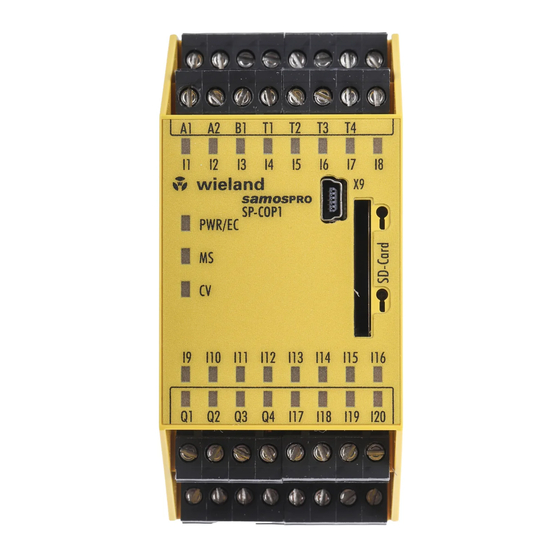
COMPACT Module SP-COP1
Description
Display Elements, Interfaces, and Terminal Description
Internal Circuits
Limited Short-Circuit Detection in the Input Circuits
Deactivating the Test Pulses at the Outputs of the SP-COP1
Single-Channel Use of Outputs on the SP-COP1
COMPACT Module SP-COP2-EN
Description
Display Elements, Interfaces, and Terminal Description
Internal Circuits
Limited Short-Circuit Detection in the Input Circuits
Deactivating the Test Pulses at the Outputs of the SP-COP2
Single-Channel Use of Outputs on the SP-COP2
COMPACT Module SP-COP2-ENI
Description
Display Elements, Error Codes, and Terminal Description
COMPACT SP-COP-CARD1 Removable Storage
SP-SDIO Input/Output Expansion Module
Description
Display Elements and Terminal Assignment
Internal Circuits
Deactivating the Test Pulses at the Outputs of the SP-SDIO
Single-Channel Use of Outputs on the SP-SDIO
SP-SDI Input/Output Expansion Module
Description
Display Elements and Terminal Assignment
Internal Circuits
SP-DIO Input/Output Expansion Module
Description
Display Elements and Terminal Assignment
Internal Circuits
4 Connecting Devices
Safety Command Devices and Electromechanical Safety Switches
Emergency Stop Buttons (E.g. SNH Series)
Electromechanical Safety Switch Without Lock (E.g. SMS Series)
Electromechanical Safety Switch with Lock (E.g. sin Series)
Enable Switch
Two-Hand Control
Type IIIA
Type IIIC
Safety Mats and Bumper
Diode Pairs for Safety Mats
Mode Selection Switch
Potential-Free Contacts
Contactless Safety Sensors
Magnetic Safety Switches (E.g. SMA Series)
Magnetic Safety Switches with Equivalent Inputs
Magnetic Safety Switches with Complementary Inputs
Inductive Safety Switches
Transponder Switches
Testable Single-Beam Safety Light Barriers
Testable Type 2 Single-Beam Safety Light Barriers
Testable Type 4 Single-Beam Safety Light Barriers
Customer-Specific Testable Single-Beam Safety Light Barriers
Information on Installing Testable Single-Beam Safety Light Barriers
ESPE - Electro-Sensitive Protective Equipment
Safety Outputs
5 Special Functions
Muting
6 Installing/Removing
Installing Modules on Standard Rail
Removing Modules from Normal Rail
7 Electrical Installation
Requirements for Electrical Installation
Internal Wiring of the Supply Voltage
8 Configuration
9 Commissioning
Total Acceptance of the Application
Tests before Initial Commissioning
10 Diagnostics
What to Do in the Event of an Error
Error Statuses
Error Displays in the State Leds, Error Messages, and Measures for
Device State and LED Displays in the COMPACT Modules
Device State and LED Displays in the Expansion Modules
Device State and LED Displays of the Expansion Module (SP-DIO)
Wieland Support
Expanded Diagnostics
11 Maintenance
Regular Testing of the Safety Equipment by Qualified Persons
Replacing Devices
Safety Measures When Replacing Devices
12 Technical Data
Samospro System Response Times
Minimum Switch-Off Time
Response Time of the State Flag
Default Values for Non-Secure or Secure Data
Safety Technology Reference Values
Samospro COMPACT (SP-Copx Without I/O Expansion)
Samospro COMPACT
Data Sheet
SP-COP1 and SP-COP2-Enx Modules
SP-SDIO Input/Output Expansion Module
SP-SDI Input/Output Expansion Module
SP-DIO Input/Output Expansion Module
Dimensional Drawings
SP-COP1-XXX / SP-COP2-XXX Controller Modules
SP-SDIO and SP-DIO Input/Output Expansion / SP-SDI Input Expansion
WKFN 2.5 E/35 GO-URL Level Terminal
13 Order Data
Samospro - COMPACT - Modules and Accessories
Modules for Contact Expansion
Other Safety-Related Products
14 Appendix
Declaration of Conformity
Checklist for Manufacturers
Complete List of Error Messages
Advertisement
Quick Links
1
Diagnostics
2
Error Statuses
Download this manual
samos ®
samos ® PRO
PRO
COMPACT-Hardware
Manual
Doc. no. BA000966
Last Update: 07/2016 (Rev. C)
Table of
Contents
Previous
Page
Next
Page
1
2
3
4
5
Advertisement
Table of Contents
Need help?
Do you have a question about the SP-COP1 and is the answer not in the manual?
Ask a question
Questions and answers
Related Manuals for Wieland SP-COP1
Controller Wieland samos PRO SP-COP1 Series Hardware Manual
(205 pages)
Control Unit Wieland Samos Pro Compact SP-COP1 Instruction Manual
Main module of the modular safety controller (37 pages)
I/O Systems Wieland SP-EN-ETC Manual
Samos pro compact (110 pages)
I/O Systems Wieland SP-SDIO Manual
Samos pro compact (110 pages)
I/O Systems Wieland SA-IN-S-K Series Translation Of The Original Instructions
Input module with hard-coding in the samos modular safety system (37 pages)
This manual is also suitable for:
Sp-sdi
Sp-cop2-en
Sp-cop2-eni
Sa-or-s1
Sa-or-s2
Sp-dio
...
Show all
Sp-profibus-dp
Sp-canopen
Sp-en-etc
Sp-sdio
Table of Contents
Save PDF
Print
Rename the bookmark
Delete bookmark?
Delete from my manuals?
Login
Sign In
OR
Sign in with Facebook
Sign in with Google
Upload manual
Upload from disk
Upload from URL


Need help?
Do you have a question about the SP-COP1 and is the answer not in the manual?
Questions and answers