
Related Manuals for Termomont TEMY PLUS P 25


Summary of Contents for Termomont TEMY PLUS P 25
- Page 1 STOVE-BOILER FOR SOLID FUELS Directions for use and assembling Customer service: Termomont d.o.o. Prhovačka bb 22310 Šimanovci tel. 022 480404, 022 480494 fax 022 480494 www.termomont.rs 30. septembar 2013...
-
Page 2: Table Of Contents
1 Technical data 1.1 Boiler properties TEMY PLUS P 25 ......1.2 On Product .......... -
Page 3: Technical Data
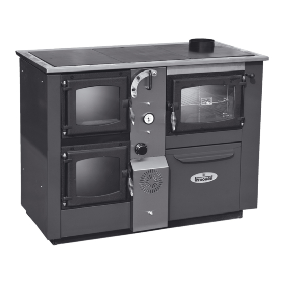
Technical data Boiler part description: 1. Heating chamber 2. Water cooled grid 3. Hot water 4. Flap 5. Flue flap 6. Oven 7. Upper grid (placing it up and down enables/disables the šummer mode") 8. Flow line 9. Return line 10. Flue 11. -
Page 4: Boiler Properties Temy Plus P
Boiler properties TEMY PLUS P 25 1. Overall nominal power (kW) 2. Necessary draught (Pa) 3. Water content (l) 4. Max working temperature 90˚C 5. Max working pressure 3 bar 6. Weight 235 kg 7. Flue diameter 148 mm 8. Width 1130 9. -
Page 5: Boiler Shipment And Storage
Boiler shipment and storage The boiler must always stand in its vertical position. The rotation of the boiler during the shipment or installation represents a serious risk and can lead to damaging the boiler. It is forbidden to place one boiler onto another. The boiler can be stored only in closed rooms with no atmospheric influence. The humidity in the storing room also must not exceed the critical value of 80%, so as not to create any condensate. - Page 6 Aeration vessel to be fitted at highest point of the system at top of boiler outlet. This should include an overflow system with valve to discharge air from the boiler to prevent overheating. A float operated valve allows water into a cistern fitted with an overflow pipe. When the system is filling, the valve remains open.
-
Page 7: Installation Method 2
2.1.2 Installation method 2 To be used in the case of the boiler being positioned and installed at a lower level than the installed pipe-work and radiators. As shown on Figure, following elements are connected along the FLOW: 1. Automatic air vent 2. -
Page 8: Filling Up The Boiler And Installation With Water
Filling up the boiler and installation with water Filling is done using the drain tap valve (to be found on the return line close to boiler). The filling process is done when no air is coming out through automatic air vent and pressure gauge is showing the value between 1,5 and 2,5 bar (closed systems). -
Page 9: Chimney
2. Heating from below – put small amount of solid fuel over the fireplace pipes (“grid”) (no ash should be present) and set up a fire. The draught regulator is at the maximum position. When the fire begins to burn, add larger amount of fuel and set draught regulator on desired temperature / position. -
Page 10: Modes Of Operation
Modes of Operation Depending on the chosen mode of operation TEMY PLUS P can perform in three ways. 1. Winter mode - Predominatly Heating Mode 2. Combined mode 3. Summer mode - Predominantly Baking Mode... -
Page 11: Overheat Protection Using The Thermostatic Valve (Closed System)
In the (predominantly) heating mode, it is necessary to pull the flue flap (position 5) then to fire the wood inside the boiler. The draught regulator should be set within range 85-95 ˚C. In the summer mode, the grid should be placed on the upper holders inside the chamber as shown on the image below. First the holders are placed and then the grid itself. -
Page 12: Boiler Cleaning And Maintenance
First connect the sensor (male thread 1/2”) on the marked position on the boiler - female thread 1/2” Now connect the cold water supply to the valve - female thread 3/4”, then connect the valve to the position 1 (cold water entrance), the boiler should have the prepared reduction 3/4”-1/2” Connect the hot water exit toward the sewerage.
Need help?
Do you have a question about the TEMY PLUS P 25 and is the answer not in the manual?
Questions and answers