Table of Contents

Related Manuals for Termomont TEMY PRO P 25


Summary of Contents for Termomont TEMY PRO P 25
- Page 1 Central heating solid-fuel boiler with a cooker TEMY PRO P 25 Technical manual for use and maintenance Prhovačka bb, 22310 Šimanovci, Serbia, Tél / Fax. +381 22 480404 +381 63 259422 podrska@termomont.rs www.termomont.rs October 2023...
-
Page 2: Table Of Contents
Contents Contents ..........................2 1 General product data ......................3 1.1 Technical data chart ..........................5 1.2 Emision values ............................6 1.3 Description of the product ........................6 2 Recommendations for shipment and storage ................. 6 2.1 Delivery ..............................6 2.2 Additional parts and documents ...................... -
Page 3: General Product Data
General product data... -
Page 5: Technical Data Chart
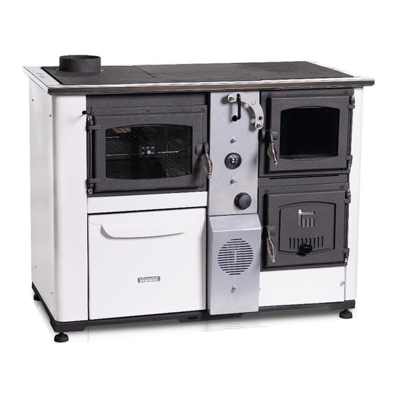
11. Working mode handle (combined, cooking, central-heating) 12. Thermometer 13. Thermomanometer 14. Safety heat-exchanger (temperature relief valve mount) 15. Lower boiler door with secondary air inlet Technical data chart Type TEMY PRO P 25 Nominal power 25 KW Power transmitted to the central heating 18 KW... -
Page 6: Emision Values
Emission values TEMY PRO P is evaluated according to European Directive 2015 :1189 and its emission values as well as boiler efficiency are officially tested and confirmed to be below prescribed limits. Results TEMY PRO P Dust [mg/Nm3] CO [mg/Nm3] OGC [mg/Nm3] NOx [mg/Nm3] Seasonal space heating energy efficiency... -
Page 7: Introduction Notes
Following parts and documents are delivered along the boiler: • A cleaning kit • Summer-mode grid • Regulation bar (mounted) • Boiler draught regulator (part of the boiler) Following parts are not delivered with the boiler: • Thermo-manometer and the safety group •... -
Page 8: Safety Remarks
An expert should be entrusted for the planning and construction of the heating system. In the case of an incorrectly planned system or the incorrect installation of the system, which can again lead to an incorrect operation of the boiler, the complete liability for the material damage and new costs arising are to be covered by the person who was entrusted with the mounting of the central heating system, and not by the boiler manufacturer, sales representative or seller. -
Page 9: Connecting To The Chimney
Connecting to the chimney This product requires a natural draught and a chimney not just to transport flue gases out of the boiler but also to create natural pressure difference necessary for boiler function. This boiler requires pressure drop of 13-15 Pa depending on the model. To reduce heat loss and due to ecological and safety factors, it is essential to have a vertical chimney connected according to the picture and, if conditions allow, the chimney must be of quality (made with ceramic segments thick up to 5 cm). - Page 10 Back-side or top-side connection to the chimney .
-
Page 11: Filling The System With Water
Filling the system with water Filling the system with water is to be done using the tap valve connection of the boiler. When filling the system with water take care that no air remains in the boiler. The filling process is done when no air is coming out through automatic air vent and pressure gauge is showing the value between 1 bar and 1,5 bar (closed systems). -
Page 12: Installation Of Temperature Relief Valve With Obligatory Filling
1) Boiler 2) Boiler valve 3) Automatic air vent 4) Thermo-manometer 5) Safety valve 6) Mix valve 7) Expansion vessel 8) Circulation pump 9) Dirt catcher The safety valve (with preset 1,5 bar threshold) should be mounted on the backside of the boiler. It is essential to have a thermometer and a manometer installed to the system (Position 4 on upper scheme) It is recommended to install a dirt catcher and also an anticondensation valve on the return... -
Page 13: Boiler Return-Line Protection Against Condensation
In the event of a rise in the temperature of the water in the boiler for any reason and if the critical value of 95-100 C is reached, the role of this valve is to open the supply channel of the cold water from the network and directly cool the water in the boiler, thus preventing a potential breakdown. -
Page 14: Modes Of Operation
1. 3-way mixing valve 2. Circulation pump 3. Thermostate The function of the mixing valve is to immediately transfer a part of hot water to the cold part of the boiler in order to reduce the temperature difference between flow and return line. Indeed, low temperature corrosion occurs when the temperature of the water in the return circuit of the heating is below the point of creation of condensation by the flue gases. - Page 15 “A” – the mode-selector “A” is the main mode controller and it moves the flap located in the upper middle part between the boiler chamber and the oven. It is also depicted on images below. This flap has “3 stages”. 1.
- Page 16 In the third and fourth scenario regulation bar “B” is REMOVED. The drawings below show the primary path of the flue gases in these cases.
- Page 17 Conclusion: by removing the regulation bar more heat will be pushed toward the cooking plate and eventually around the oven. This scenario can be useful when cooking and baking are primary function. Summer mode: Please note there is a a so-called summer-mode grid delivered with this product. The purpose of this grid is to shorten the heating chamber and avoid unnecessary heating.
-
Page 18: Boiler Cleaning And Maintenance
Boiler cleaning and maintenance Regular maintenance and cleaning of solid fuel boilers is necessary to ensure product functionality and long-life operation. Boiler cleaning consists of following operations: 1. Emptying ash-trail of the boiler 2. Removing ash from the bottom part of the boiler 3. - Page 19 THANK YOU FOR READING THIS DOCUMENT CAREFULLY – IF YOU HAVE ADDITIONAL QUESTIONS FEEL FREE TO CONTACT US OR YOUR LOCAL RESELLER. Prhovačka bb, 22310 Šimanovci, Serbia Tél / Fax. +381 22 480404 +381 63 259422 podrska@termomont.rs www.termomont.rs...
Need help?
Do you have a question about the TEMY PRO P 25 and is the answer not in the manual?
Questions and answers