Advertisement
Table of Contents
- 1 Basic Boiler Data
- 2 Technical Data According to en 303-5
- 3 Boiler Parts
- 4 Boiler Parts - Variation TOBY B 12 SET
- 5 Delivery Range
- 6 Safety Remarks
- 7 Connection to the Chimney
- 8 Filling the System with Water
- 9 Installation Method 1
- 10 Installation Method 2
- 11 Use of Temperature Relief Valve with Obligatory Filling
- 12 Return Line Protection against Condensation
- 13 Boiler Cleaning and Maintenance
- 14 Weekly Cleaning of the Heat Exchangers
- Download this manual
Advertisement
Table of Contents

Related Manuals for Termomont TOBY B 12


Summary of Contents for Termomont TOBY B 12
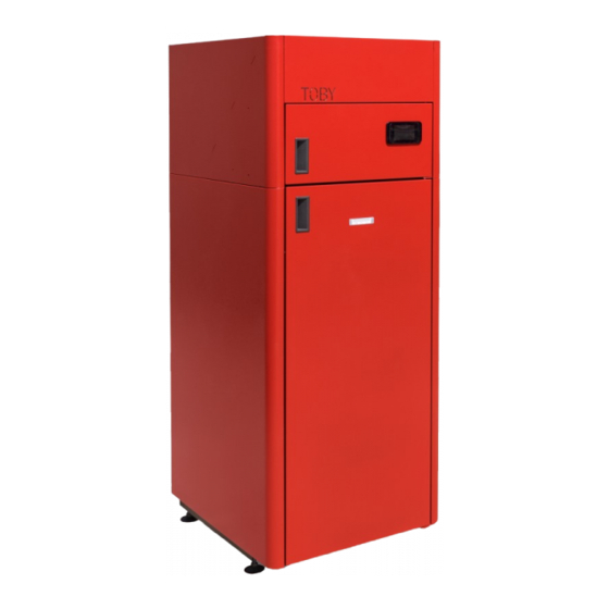
- Page 1 TOBY B 12-17-21 Compact size wood pellet boiler DIRECTIONS for use and maintenance Prhovačka bb 22310 Šimanovci, Srbija Tel/Fax. +381 22 480404 +381 63 259422 podrska@termomont.rs www.termomont.rs December 13, 2016...
- Page 2 1.3 Boiler parts ..........1.4 Boiler parts - variation TOBY B 12 SET ......
-
Page 3: Basic Boiler Data
Basic Boiler data Type Width B (mm) Height H (mm) Length L (mm) B 12 1435/1465 B 17 1435/1465 B 20 1495/1525... -
Page 4: Technical Data According To En 303-5
Technical data according to EN 303-5 Boiler type TOBY B Total power 13.5 KW 17,5 KW 21 KW Power range 3.6-13.5 KW 4.8 - 17.5 KW 6.3 - 20,7 KW Min power pellet consumptioni min 0.8 kg/h min 1.1 kg/h min 1.4 kg/h Max power pellet consumption max 2.8 kg/h... -
Page 5: Boiler Parts
Boiler parts 1. Door housing plates 2. Outter door 3. Visor 4. Burner (pot) 5. Pellet doser tube 6. Opening for cleaning 7. Opening threads 8. Boiler housing (lower carrier) 9. Boiler housing (upper carrier) 10. Boiler small door with display 11. Boiler Tubulators Opening 12. Boiler housing mask 13. Lateral sides of the housing... - Page 6 14. Upper lateral boiler housing plate 15. Pellet magazine slope 16. Hole for pellet flow 17. Fixed opening 18. Opening hinges 19. Upper back housing plate 20. Back housing plate 21. Revision opening at back housing plate 22. Small pellet magazine 23. Pellet auger with motor 24. Ignitor 25. Ventilator 26. Flue tube 27. Basement 28.
-
Page 7: Boiler Parts - Variation Toby B 12 Set
Boiler parts - variation TOBY B 12 SET 14. Upper lateral boiler housing plate 15. Pellet magazine slope 16. Hole for pellet flow 17. Fixed opening 18. Opening hinges 19. Upper back housing plate 20. Back housing plate 21. Revision opening at back housing plate 22. -
Page 8: Delivery Range
The rotation of the boiler during the shipment or installation represents a serious risk and can lead to damaging the boiler. It is forbidden to place one boiler onto another. The boiler can be stored only in closed rooms with no atmospheric influence. The humidity in the storing room also must not exceed the critical value of 80%, so as not to create any condensate. -
Page 9: Safety Remarks
Clean the boiler on a regular base. An expert should be entrusted with the mounting of the heating and the initial operation. This must be a person who will take over the responsibility and guarantee the correct operation of the boiler and of the complete central heating system. -
Page 10: Connection To The Chimney
Front side and lateral side(s) should have free access. Otherwise, follow the measures depicted in the drawing, since additional space is required to place the tube for flue gases behind the boiler. Boiler base must be stable and made of fireproof material. Connection to the chimney Sub-pressure pellet boilers require pressure difference of at least 10 ( 3) Pa in order to ensure safe and... -
Page 11: Filling The System With Water
Legend: 1) Chimney 2) Gasket 3) Fireproof protection cap 4) Chimney diameter not greater than 200x200mm and not higher than 5-6m Filling the system with water Filling the system with water is to be done using the tap valve connection of the boiler. When filling the system with water take care that no air remains in the boiler. -
Page 12: Installation Method 1
boiler) and it must be mounted near the boiler. It is essential to have a thermometer and a manometer installed to the system. It is recommended to install an anticondensation valve on the return line. (3-way mixing valve). It is also recommended to mount a filth catcher on the return line. Depending on the position of the boiler in relation to the pipe-work and the radiators –... -
Page 13: Installation Method 2
5.4.2 Installation method 2 To be used in the case of the boiler being positioned and installed at a lower level than the installed pipework and radiators. As shown on Figure, following elements are connected along the FLOW: 1. Automatic air vent 2. -
Page 14: Use Of Temperature Relief Valve With Obligatory Filling
Use of temperature relief valve with obligatory filling The temperature relief valve (shown below) must be present in the system. The valve must be installed by a qualified technician in accordance with the instructions given in the manual from the producer of the valve. - Page 15 When using open system on the FLOW line following elements are to be installed: safety pipework for the open expansion vessel, boiler valve. On the RETURN line come safety return line of the open expansion vessel, boiler valve and circulation pump valves. Open expansion vessel is connected to the hot-water distribution pipes (FLOW and RETURN) as shown on Figure –...
-
Page 16: Return Line Protection Against Condensation
Return line protection against condensation Every boiler is sensitive to condensation if the return line water temperature is too low. In order to avoid it is necessary to mount the mixing valve to this boiler. 1. 3-end mixing valve 2. Flow line 3. Return line The purpose of this valve is to transmit a portion of the hot water to the return line cold water in order to compensate the temperature difference between the flow and return line. -
Page 17: Boiler Cleaning And Maintenance
Boiler cleaning and maintenance Regular maintenance and cleaning of pellet boilers is necessary to ensure product functionality and long- life operation. 1. Emptying ash-trailers of the boiler 2. Removing ash from the bottom part of the boiler chamber 3. Cleaning of burner pot 4. - Page 18 Open the lower, chamber door with the boiler KEY. Open the main boiler door and remove the ash-tray outside the boiler. Also remove burner pot, remove the ash from the pot int the ash-tray first, then empty the ash-tray. CAUTION: SOME PARTS MAY BE HOT! Clean the area where burner pot is placed.
- Page 19 If no vacuum cleaner is present, use the hand tools as shown below. Release the screw-balls that hold the plate below. Clean the area inside with the ash cleaner or using manual tools. When screwing back the holders, screw completely, so that no air can pass inside. Ukoliko ne posedujetevIf no vacuum cleaner is present, use the hand tools as shown below.
-
Page 20: Weekly Cleaning Of The Heat Exchangers
Weekly cleaning of the heat exchangers Necessary equipment: Gloves, boiler KEY (delivered with the boiler). Make sure you perform this operation while boiler is cold. Open the doors on the top panel of the boiler. There are two bars coming out. Now take the boiler KEY, mount on the bar and move up-down to release the ash from the heat exchanger tubulators. - Page 21 Metal cap with tubulator lifters and one screw in the middle is visible. The insulation coat is attached below this metal cap. To unsrew the cap use boiler KEY. Put the metal cap aside. make sure you make no damage to the stone-wall insulation below.
- Page 22 With fork-key size 13 or boiler KEY, unscrew the upper cover of the heating chamber. Lift the cover and put it on side. Perform detailed cleaning of all parts that can be accessed. Remove the ash. The use of the ash-vacuum cleaner would make this job faster and easier.
- Page 23 After the cleaning put back the cover and screw the holders. Put everything back in its place.
Need help?
Do you have a question about the TOBY B 12 and is the answer not in the manual?
Questions and answers