Sign In
Upload
Download
Table of Contents
Contents
Add to my manuals
Delete from my manuals
Share
URL of this page:
HTML Link:
Bookmark this page
Add
Manual will be automatically added to "My Manuals"
Print this page
×
Bookmark added
×
Added to my manuals
Manuals
Brands
Termomont Manuals
Boiler
TOBY 20
Directions for use and maintenance
Termomont TOBY 20 Directions For Use And Maintenance
Wood pellets boiler
Hide thumbs
1
Table Of Contents
2
3
4
5
6
7
8
9
10
11
12
13
14
15
16
17
18
19
20
page
of
20
Go
/
20
Contents
Table of Contents
Bookmarks
Table of Contents
Table of Contents
1 Boiler Data
Technical Data Chart According to en 303-5
On Product
2 Directions for Storage and Transport
Delivery Form
Delivery Range
3 Introductory Remarks
4 Safety Remarks
5 Boiler Placement
Boiler Room
Chimney
Filling the System with Water
Connecting the Boiler with a Closed Central Heating System
Installation Method 1
Installation Method 2
Use of Temperature Relief Valve with Obligatory Filling
Fitting the Boiler to an Open Central Heating System
6 Mixing Valve
7 Control Panel
Boiler Cleaning and Maintenance
A Emissions Test Report
Advertisement
Quick Links
1
Technical Data Chart According to en 303-5
2
Installation Method 1
3
Mixing Valve
4
Control Panel
5
Boiler Cleaning and Maintenance
Download this manual
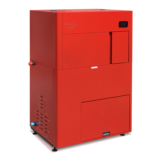
TOBY 20-30-40-50 KW
Wood pellets boiler
DIRECTIONS
for use and maintenance
Prhovačka bb 22310 Šimanovci, Srbija
Tel/Fax. +381 22 480404 +381 63 259422
podrska@termomont.rs www.termomont.rs
November 15, 2016
Table of
Contents
Previous
Page
Next
Page
1
2
3
4
5
Advertisement
Table of Contents
Need help?
Do you have a question about the TOBY 20 and is the answer not in the manual?
Ask a question
Questions and answers
Related Manuals for Termomont TOBY 20
Boiler Termomont TPK 20 Instruction Manual
(18 pages)
Boiler Termomont TKK3 max 100 Instruction Manual
(9 pages)
Boiler Termomont TKK3 max Series Instruction Manual
Solid fuel hot water boiler 100-300 kw (10 pages)
Boiler Termomont TKU3 PELLET 20 Instruction Manual
Wood pellet boiler with wood pellet burner termec series (16 pages)
Boiler Termomont TOBY 30 Directions For Use And Maintenance
Wood pellets boiler (20 pages)
Boiler Termomont TOBY B 14 Directions For Use And Maintenance
Automatic self-cleaning wood pellet boiler "compact" (24 pages)
Boiler Termomont TKU3-W PRO Series Instructions Manual
Three-pass solid fuel hot water boiler (12 pages)
Boiler Termomont TKU3-W PRO Instructions For Usage And Installation
Three-pass solid fuel hot water boiler (13 pages)
Boiler Termomont TOP-W 25 KW Instructions Manual
Three-pass solid fuel boiler with fan control (11 pages)
Boiler Termomont TOBY B 12 Directions For Use And Maintenance
Compact size wood pellet boiler (23 pages)
Boiler Termomont TOBY B 12 Directions For Use Manual
Compact size wood pellet boiler (24 pages)
Boiler TERMOMONT IGNIS Instructions Manual For Usage And Maintenance
Wood logs boiler with a gasification effect 20-40 kw (14 pages)
Boiler Termomont TEMY PLUS P 25 Directions For Use And Assembling
Stove-boiler for solid fuels (12 pages)
Boiler Termomont TEMY ES 10 Technical Manual
Central heating solid-fuel boiler with a cooking plate (14 pages)
Boiler Termomont TEMY PRO P 25 Manual For Use And Maintenance
Central heating solid-fuel boiler with a cooker (19 pages)
This manual is also suitable for:
Toby 30
Toby 40
Toby 50
Table of Contents
Print
Rename the bookmark
Delete bookmark?
Delete from my manuals?
Login
Sign In
OR
Sign in with Facebook
Sign in with Google
Upload manual
Upload from disk
Upload from URL


Need help?
Do you have a question about the TOBY 20 and is the answer not in the manual?
Questions and answers