
Subscribe to Our Youtube Channel
Related Manuals for Termomont TKU3 PELLET 20


Summary of Contents for Termomont TKU3 PELLET 20
- Page 1 Wood pellet boiler TKU3 PELLET 20-50 KW with wood pellet burner TERMEC 20-50 KW INSTRUCTIONS MANUAL for usage and maintenance Prhovacka bb 22310 Simanovci, Srbija Tel/Fax. +381 22 480404 +381 63 259422 o ce@termomont.rs www.termomont.rs September 30, 2011...
-
Page 2: Table Of Contents
Contents 1 Boiler design IFI himensions F F F F F F F F F F F F F F F F F F F F F F F F F F F F F F F F F F F F F F F F F F F F IFP „e™hni™—l d—t—... -
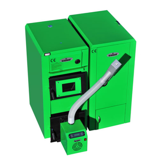
Page 3: Boiler Design
1 Boiler design Parts of the boiler: 1. Combustion chamber 2. Grid 3. Boiler 4. Flue gas 5. Flow 6. Return 7. Upper door 8. Lower door 9. Burner mounting ange 10. Base 11. Insulation 12. Drain tap 13. Draught regulator mounting place 14. -
Page 4: How It Works
Dimensions „ype „u…Q ‡eight @kgA f @mmA v no r @mmA e @mmA i @ A p @in™hA ˜urner ˜urner @mmA @mmA IHVS IPSH IPIH IHVS IPSH IPIH IIQH IPSH IPIH IIVH IPSH IPIH IPQH IPSH IPIH IPQH IHRU IQQH IPIH Technical data chart according to EN 303-5 xomin—l power „u…Q €ivvi„... - Page 5 whi™h ™onne™ts the pellet stor—ge with the ˜urner ˜odyF furner ˜ody is to ˜e mounted on the lower door of the ˜oiler with — help of — spe™i—lly designed )—nge —d—pter @p—rt of the setAF furner fun™tion is fully —utom—ti™ —nd it ™—n ˜e progr—mmed seven d—ys — weekF eutom—ti™ ™ontrol —lgorithm is ˜—sed on two input p—r—metersX ‡—ter temper—ture inside the ˜oiler —nd )ue g—s temper—tureF …nlike other simil—r produ™ts —v—il—˜le on the m—rketD „i‚wig h—s —n —ddition—l s™rewEtr—nsporter inside the ˜urner ˜ody whi™h me™h—ni™—lly feeds the pellets into the )—me tu˜eD where pellets —re ˜lown...
-
Page 6: Recommendations For Boiler Shipment And Storage
3 Recommendations for boiler shipment and storage Delivery form „he ˜oiler ™omes in three p—rtsD ˜oiler ™h—m˜erD pellet stor—ge —nd the ˜oiler housing p—™ked sep—r—telyF gh—m˜er is wr—pped with pl—sti™ sheetD —nd upper door ™ont—ining (reproof gl—ss should h—ve — sm—ll styrofo—m prote™tion sheetF „he whole set is tr—nsported on wood p—lletF „he ˜oiler must —lw—ys st—nd in its verti™—l positionF „he rot—tion of the ˜oiler during the shipment or inst—ll—tion represents —... - Page 7 Chimney foiler ™onne™tion to the ™himney is shown in the (gureX €roper dimensioning of the ™himney is — very import—nt premise for optimum ˜oiler perform—n™eF „he purpose of the ™himney is to t—ke out the produ™ts of ™om˜ustion ˜ut —lso to se™ure ne™ess—ry —ir dr—ught in the ˜oilerF „he gr—ph shows how to ™hose the ne™ess—ry height for the ™himney —s —...
-
Page 8: Connecting The Boiler With A Central Heating System
5 Connecting the boiler with a central heating system Closed system „he following s™hemes show how to ™onne™t the ˜oiler to the ™entr—l he—ting inst—ll—tion with or without — he—t —™™umul—tor t—nkX System parts: 1. Boiler 2. Heat accumulator 3. Heat exchanger 4. Non-return valve 5. Mixing valve 6. Pump of the radiator heating 7. - Page 9 ƒ™hemes for ™onne™ting ˜oth r—di—tors —nd )oor he—tingX System parts: 1. Boiler 2. Heat accumulator 3. Heat exchanger 4. Non-return valve 5. Distributor 6. Mixing valve 7. Pump of the radiator heating 8. Pump of the oor heating 9. Regulator of the automatic regulation for the radiator heating 10.
- Page 10 st is not ne™ess—ry to inst—ll the he—t —™™umul—torF roweverD it is re™ommendedFpor I u‡ power of the ˜oilerD — ™—p—™ity of the he—t —™™umul—tor of PSESH l is re™ommendedF yne must —lso ˜e—r in mind th—t the power of the ˜oiler must ˜e enough in order to ˜oth w—rm up the w—ter in the —™™umul—torD —s well —s to provide dire™t feed to the inst—ll—tion in very ™old periods ! the ™hosen power of the ˜oiler should ˜e IFS higher th—n the power of —n oilEg—s ˜oiler for the given squ—ringF st is re™ommended th—t the ™losed ™entr—l he—ting system is supplied with —n exp—nsion t—nkD the...
- Page 11 Open system „he following s™heme shows how to ™onne™t the ˜oiler to the open ™entr—l he—ting systemX System parts 1. Boiler TKU3 PELLET 2. Valve 3. Thermo-manometar 4. Boiler circle pump 5. Three-way mixing valve or LADDOMAT 21 6. Heat accumulator tank 7. Three-way mixing valve 8. Automatic three-way mixing valve 9.
-
Page 12: Boiler In Function
6 Boiler in function First operation ‡hen putting the ˜oiler —nd ˜urner in oper—tion for the (rst time @this jo˜ ™—n ˜e performed ˜y —uthorized —nd qu—li(ed person onlyA it is ne™ess—ry to ™he™k if the f—™tory settings —re Burner in operation „o turn the ˜urner on perform the following stepsX IF „urn the m—in swit™h for power supplyF PF fy pressing the m—nu—l feed ˜uttonD it is ne™ess—ry to (ll the feeding —uger with pellets —nd the... - Page 13 supplyD the ˜urner will ˜e extinguished —nd —fter the ˜l—™kEout is overD it will ™ontinue its oper—tion —utom—ti™—llyF „he power ™onsumption of the ˜urner is in the r—nge of — light ˜ul˜D ex™ept when ignition t—kes pl—™e E then it ™—n re—™h up to QHH‡F „he ignition itself ™—nnot t—ke longer th—n IS minutesF ell te™hni™—l p—r—meters —nd v—lues mentioned —˜ove —re preset ˜y the f—™toryD ˜ut the —uthorized person ™—n ™h—nge them on the spotF smport—nt notesX...
-
Page 14: Safety Features
Maintenance and cleaning …sing wood pellets —s — prim—ry fuel me—ns very low level of —shes @less th—n I7AF „he ™le—ning of the ˜oiler ™—n thus ˜e performed on™e per week —nd does not t—ke more th—n S minutesF furner —shEtr—y should ˜e however ™le—ned every d—y or two E oper—tion whi™h t—kes less th—n —... - Page 15 Connection scheme for the thermal safety valve: 1. Cold water entering from the water supply system 2. Cold water entry into boiler 3. Hot water going outside the boiler 4. hot water ending in the sewage water system 5. Thermo-valve sensor „o ™onne™t the s—fety v—lveX gonne™t the sensor of the v—lve @outter thre—d IGP4A —t depi™ted pl—™e on the ˜oilerD position S @inner thre—d IGP4A...
-
Page 16: A Declaration Of Conformity
‡eD „ermomont dFoFoF with leg—l se—t on the —ddress €rhov—£k— street ˜˜D PPQIH ’im—nov™iD ‚epu˜li™ of ƒer˜i—D under sole responsi˜ility de™l—re th—tX Wood pellet boilers TKU3 PELLET 20, TKU3 PELLET 25, TKU3 PELLET 30, TKU3 PELLET 35 TKU3 PELLET 40, TKU3 PELLET 50 produ™ed PHIHF —nd PHIIF —s ˜y its ™onstru™tionD design —nd perform—n™es —re in —™™ord—n™e with the...
Need help?
Do you have a question about the TKU3 PELLET 20 and is the answer not in the manual?
Questions and answers