Sign In
Upload
Download
Table of Contents
Contents
Add to my manuals
Delete from my manuals
Share
URL of this page:
HTML Link:
Bookmark this page
Add
Manual will be automatically added to "My Manuals"
Print this page
×
Bookmark added
×
Added to my manuals
Manuals
Brands
Bosch Manuals
Accessories
ISC-CDL1-WA15G
Reference manual
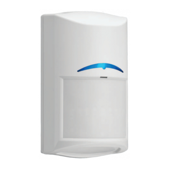
Bosch ISC-CDL1-WA15G Reference Manual
Commercial series tritech+ motion detector with anti-mask
Hide thumbs
Also See for ISC-CDL1-WA15G
:
Installation manual
(4 pages)
1
2
Table Of Contents
3
4
5
6
7
8
9
10
11
12
13
14
15
16
17
18
19
20
21
22
23
24
25
26
27
28
29
30
31
32
33
34
35
page
of
35
Go
/
35
Contents
Table of Contents
Troubleshooting
Bookmarks
Table of Contents
Table of Contents
Safety
Introduction
About Documentation
Bosch Security Systems, Inc. Product Manufacturing Dates
Detector Overview
Installation Considerations
Installation
Self-Locking Cam
Install Options
Wire Knockouts
Bubble Level
Wiring
Wiring Overview
Input Power Terminals
Alarm Terminals
Tamper Terminals
Trouble Terminals
EOL Resistors Overview
EOL Resistor Loop Combinations
Single EOL Loop - Alarm and Tamper
Double EOL Loop - Alarm and Tamper
Double EOL Loop - Alarm and Tamper with Separate Trouble Input
Triple EOL Loop - Alarm, Tamper, and Trouble Input
Configuration and Walk Test
Look-Down Zone
Walk Test LED
Walk Test
Establish the PIR and Microwave Coverage
Establish the Coverage Pattern
Adjustable Cloak and Camouflage Detection Technology Sensitivity
Adjustable Microwave Sensitivity
Self Test
Troubleshooting
Motion Detector Does Not Appear to Respond to Motion
Motion Detector Is in Continuous Alarm
Motion Detector Does Not Appear to Detect Motion in the Space Directly under It
Motion Detector Does Not Appear to Detect Motion Near the Edge of the Coverage Area
Motion Detector Does Not Appear to Detect Motion in the Farther Section of the
Motion Detector LED Flashes Continuously
Motion Detector LED Flashes Three Times in a Row Repeatedly
Motion Detector LED Flashes Four Times in a Row Repeatedly
Motion Detector LED Flashes Five Times in a Row Repeatedly
Coverage Pattern
Advertisement
Quick Links
1
Installation
2
Wiring
3
Wiring Overview
Download this manual
Commercial Series TriTech+
Motion Detector with Anti-mask
ISC-CDL1-WA15G, ISC-CDL1-WA15G-CHI, ISC-CDL1-WA15H,
ISC-CDL1-WA15K, ISC-CDL1-WA12G, ISC-CDL1-WA12G-CHI
en
Reference Guide
Available from A1 Security Cameras
www.a1securitycameras.com email: sales@a1securitycameras.com
Table of
Contents
Previous
Page
Next
Page
1
2
3
4
5
Advertisement
Table of Contents
Need help?
Do you have a question about the ISC-CDL1-WA15G and is the answer not in the manual?
Ask a question
Questions and answers
Related Manuals for Bosch ISC-CDL1-WA15G
Security Sensors Bosch ISC-CDL1-WA15H Installation Manual
Commercial series tritech+ detector with anti-mask (4 pages)
Accessories Bosch ISM-BLQ1 Installation Instructions
Installation instructions (4 pages)
Accessories Bosch ISC-PDL1-W18G Installation Instructions Manual
Professional series dual detector (12 pages)
Accessories Bosch ISC-CDL1-WA12G Reference Manual
Commercial series tritech+ motion detector with anti-mask (35 pages)
Accessories Bosch ISC-PPR1-W16 Installation Instructions Manual
Commercial pir (8 pages)
Accessories Bosch ISC-SK10 Installation Manual
Shock sensor (2 pages)
Accessories Bosch ISW-EN1247 Installation Manual
Glassbreak sensor-transmitter (2 pages)
Accessories Bosch IMSA GT Class Scrutineering System Manual
(38 pages)
Accessories Bosch MSE-LZ Installation Manual
Magnetic contact (6 pages)
Accessories Bosch IVAS Operating Instructions Manual
Sensor device (ethernet) (21 pages)
Accessories Bosch Rexroth ID 15 Assembly Instructions Manual
(44 pages)
Accessories Bosch ISM-BLP1-P Quick Start Manual
(4 pages)
Accessories Bosch IVAS 0273600075 Operating Instructions Manual
Sensor device (ethernet) (37 pages)
Accessories Bosch ISC-PMC-S2S Installation Manual
Magnetic contact (6 pages)
Accessories Bosch Rexroth HEDE 10-3 Series Operating Instructions Manual
Electronic pressure sensor with switching and analog output (48 pages)
Accessories Bosch Rexroth BS 1/M Assembly Manual
Transverse conveyor (56 pages)
This manual is also suitable for:
Isc-cdl1-wa15g-chi
Isc-cdl1-wa15k
Isc-cdl1-wa12g
Isc-cdl1-wa12g-chi
Isc-cdl1-wa15h
Table of Contents
Save PDF
Print
Rename the bookmark
Delete bookmark?
Delete from my manuals?
Login
Sign In
OR
Sign in with Facebook
Sign in with Google
Upload manual
Upload from disk
Upload from URL


Need help?
Do you have a question about the ISC-CDL1-WA15G and is the answer not in the manual?
Questions and answers