Sign In
Upload
Manuals
Brands
IEI Technology Manuals
Computer Hardware
NANO-LX
IEI Technology NANO-LX LX 800 SBC Manuals
Manuals and User Guides for IEI Technology NANO-LX LX 800 SBC. We have
2
IEI Technology NANO-LX LX 800 SBC manuals available for free PDF download: User Manual
IEI Technology NANO-LX User Manual (198 pages)
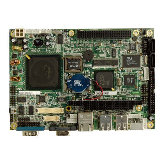
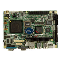
EPIC AMD Geode LX 800 SBC with VGA / LVDS / TFT Single GbE, SATA RAID, USB 2.0 and Audio
Brand:
IEI Technology
| Category:
Motherboard
| Size: 9 MB
Table of Contents
Table of Contents
5
User Manual
1
Packing List
4
1 Introduction
17
Nano-Lx Cpu Board Overview
18
Figure 1-1: NANO-LX EPIC SBC
18
NANO-LX CPU Board Applications
18
NANO-LX CPU Board Benefits
18
NANO-LX CPU Board Features
19
Nano-Lx Sbc Overview
20
Figure 1-2: NANO-LX CPU Board Overview (Front Side)
20
Figure 1-3: NANO-LX CPU Board Overview (Solder Side)
20
NANO-LX CPU Board Connectors
21
Technical Specifications
22
Compatible Operating Systems and Memory Modules
23
Table 1-1: Technical Specifications
23
Memory Module
24
Operating System
24
Table 1-2: Compatible Memory Modules
24
2 Detailed Specifications
25
Overview
26
Dimensions
26
Board Dimensions
26
Figure 2-1: NANO-LX Dimensions (MM)
26
External Interface Panel Dimensions
27
Data Flow
27
Figure 2-2: External Interface Panel Dimensions (MM)
27
Cpu Support
28
AMD ® Geode™ LX800 500Mhz Overview
28
Figure 2-3: Data Flow Block Diagram
28
AMD ® Geode™ LX800 500Mhz Display Support
29
AMD ® Geode™ LX800 500Mhz Graphics Processor
29
AMD ® Geode™ LX800 Memory Support
29
Table 2-1: Geode LX Graphics Features
30
AMD ® Geode™ LX800 500Mhz Power Management
31
System Chipset
31
Geodelink™ Interface Unit
31
AMD ® Geode™ CS5536 ATA-6 Controller
32
AMD ® Geode™ CS5536 Audio Codec 97 (AC'97) Controller
32
Table 2-2: Supported HDD Specifications
32
AMD ® Geode™ CS5536 Flash Interface
34
AMD ® Geode™ CS5536 Serial Communications
34
AMD ® Geode™ CS5536 USB Controller
34
AMD ® Geode™ CS5536 Real Time Clock
35
Bios
35
Geodelink™ PCI Bridge
35
Overview
35
10/100M Ethernet
36
PCI to ISA Bridge
37
Environmental and Power Specifications
37
System Monitoring
37
Operating Temperature and Temperature Control
38
Power Consumption
38
Table 2-3: Power Consumption
38
3 Unpacking
39
Anti-Static Precautions
40
Unpacking
40
Unpacking Precautions
40
Unpacking Checklist
41
Package Contents
41
Table 3-1: Package List Contents
42
Optional Items
43
Table 3-2: Package List Contents
43
4 Connectors and Jumpers
44
Peripheral Interface Connectors
45
Figure 4-1: Connector and Jumper Locations (Front Side)
45
NANO-LX SBC Layout
45
Figure 4-2: Connector and Jumper Locations (Solder Side)
46
Peripheral Interface Connectors
46
Table 4-1: Peripheral Interface Connectors
47
Onboard Jumpers
48
Rear Panel Connectors
48
Table 4-2: Rear Panel Connectors
48
Table 4-3: Onboard Jumpers
48
Internal Peripheral Connectors
49
ATX Connector
49
Figure 4-3: CN3 Connector Location
49
Table 4-4: CN3 Connector Pinouts
49
ATX Power Button
50
Audio CD-In Connector
50
Figure 4-4: CN5 Connector Location
50
Table 4-5: CN5 Connector Pinouts
50
Audio Connector
51
Figure 4-5: CN8 Connector Location
51
Table 4-6: CN8 Connector Pinouts
51
Battery Connector
52
Figure 4-6: CN9 Connector Location
52
Table 4-7: CN9 Connector Pinouts
52
Compactflash® Connector
53
Figure 4-7: BT1 Connector Location
53
Table 4-8: BT1 Connector Pinouts
53
Table 4-9: CN35 Connector Pinouts
54
Figure 4-8: CN35 Connector Location
55
Digital Input Output Connector
56
Fan Connector
56
Figure 4-9: CN18 Connector Location
56
Table 4-10: CN18 Connector Pinouts
56
FDD Connector
57
Figure 4-10 CN4 Connector Location
57
Table 4-11 CN4 Connector Pinouts
57
Figure 4-11: CN34 Connector Location
58
Table 4-12 CN4 Connector Pinouts
58
IDE Interface Connector
59
Table 4-13: CN13 Connector Pinouts
59
Figure 4-12: CN13 Connector Location
60
Inverter Connector
60
Figure 4-13: CN26 Connector Location
61
Infrared Connector
61
Table 4-14: CN26 Connector Pinouts
61
Figure 4-14: CN32 Connector Location
62
Keyboard/Mouse Connector
62
Table 4-15: CN32 Connector Pinouts
62
Table 4-16: CN30 Connector Pinouts
62
Figure 4-15: CN30 Connector Location
63
LED Power Connector
63
Table 4-17: CN12 Connector Pinouts
63
Figure 4-16: CN12 Connector Location
64
LVDS LCD Panel Connector
64
Table 4-18: CN23 Connector Pinouts
64
Figure 4-17: CN23 Connector Location
65
Parallel Port Connector
65
Figure 4-18: CN20 Connector Location
66
PC/104-Plus Connector
66
Table 4-19: CN20 Connector Pinouts
66
Table 4-20: CN7 (PC/104) Connector Pinouts
68
Figure 4-19: CN7 Connector Location
69
Power Connector
69
Table 4-21: CN7 (PCI-104) Connector Pinouts
69
Table 4-22: CN2 Connector Pinouts
69
Figure 4-20: CN2 Connector Location
70
Power Input Connector
70
Table 4-23: CN25 Connector Pinouts
70
Figure 4-21: CN25 Connector Location
71
Reset Button Connector
71
Table 4-24: CN6 Connector Pinouts
71
Figure 4-22: CN6 Connector Location
72
SATA Drive Ports
72
Table 4-25: CN10, CN11 Connector Pinouts
72
Figure 4-23: CN10, CN11 Connector Locations
73
SATA Power Connector
73
Figure 4-24: CN38 Connector Location
74
Serial Communications Connector
74
Table 4-26: CN38 Connector Pinouts
74
Figure 4-25 CN14, CN15, CN16, CN17, CN19 Connector Locations
75
Table 4-27: CN14, CN15, CN16, CN17 Connector Pinouts
75
Table 4-28: CN19 Connector Pinouts
75
TFT TTL LCD Connector
75
Table 4-29: CN22 Connector Pinouts
76
External (Rear Panel) Connectors
77
Figure 4-26 CN22 Connector Locations
77
Figure 4-27: NANO-LX CPU Board Rear Panel
78
Figure 4-28: COM1 Pinout Locations
78
Serial Connector (COM1)
78
Table 4-30: COM1 Pinouts
78
Ethernet Connector
79
Figure 4-29: CN24 Connector
79
Table 4-31: CN24 Connector Pinouts
79
VGA Connector
79
Figure 4-30: CN27 Connector
80
Table 4-32: CN27 Connector Pinouts
80
Table 4-33: CN27 Connector Leds
80
USB Combo Connectors
80
Figure 4-31: CN31 Pinout Locations
81
Keyboard/Mouse Connector
81
Table 4-34: CN28, CN29 Connector Pinouts
81
Table 4-35: CN31 Pinouts
81
5 Installation and Configuration
82
Anti-Static Precautions
83
Installation Considerations
84
Installation Notices
84
Installation Checklist
85
Unpacking
86
Unpacking Checklist
86
Unpacking Precautions
86
So-DIMM Installation
87
Figure 5-1: SO-DIMM Installation
87
Cf Card Installation
88
Figure 5-2: CF Card Installation
88
Jumper Settings
89
Figure 5-3: Jumper Locations
89
Table 5-1: Jumpers
89
Figure 5-4: Jumper Locations
90
LCD Panel Shift Clock Jumper
90
COM1/2 Port RI and Voltage Selection Jumper (Optional)
91
Table 5-2: JP1 Jumper Settings
91
Table 5-3: JP2 Jumper Settings
91
UART Port a RS-422/485 Select Jumper
91
AT/ATX Power Mode Select Jumper
92
Table 5-4: JP3 Jumper Settings
92
Table 5-5: JP4 Jumper Settings
92
PC/104-Plus SERIRQ Select Jumper
93
PC/104-Plus VIO Voltage Select Jumper
93
Table 5-6: JP5 Jumper Settings
93
Table 5-7: JP6 Jumper Settings
93
LCD Panel (LVDS/TTL) Voltage Select Jumper
94
Chassis Installation
94
Airflow
94
Table 5-8: JP7 Jumper Settings
94
Motherboard Installation
95
Internal Peripheral Device Connections
95
Peripheral Device Cables
95
Table 5-9: IEI Provided Cables
95
ATA Flat Cable Connection
96
Figure 5-5: IDE Cable Connection
96
AT Power Connection
97
Figure 5-6: Power Cable to Motherboard Connection
97
Audio Kit Installation
98
Figure 5-7: Connect Power Cable to Power Supply
98
Figure 5-8: Audio Kit Cable Connection
99
Parallel Port Cable
99
Figure 5-10: Connect the LPT Device
100
Figure 5-9: LPT Cable Connection
100
Single RS-232 Cable
100
Figure 5-11: Single RS-232 Cable Installation
101
SATA Drive Connection
101
Figure 5-12: SATA Drive Cable Connection
102
External Peripheral Interface Connection
103
Figure 5-13: SATA Power Drive Connection
103
Figure 5-14: LAN Connection
104
LAN Connection (Single Connector)
104
PS/2 Keyboard/Mouse Connection
104
Figure 5-15: PS/2 Connector
105
Figure 5-16: Serial Device Connector
106
Serial Device Connection
106
USB Connection (Dual Connector)
106
Figure 5-17: USB Connector
107
VGA Monitor Connection
107
Figure 5-18: VGA Connector
108
6 Award Bios Setup
109
Introduction
110
Starting Setup
110
Using Setup
110
Getting Help
111
Main BIOS Menu
111
Table 6-1: BIOS Navigation Keys
111
Unable to Reboot after Configuration Changes
111
BIOS Menu 1: Awardbios CMOS Setup Utility
112
Exit Without Saving
113
Load Fail-Safe Defaults
113
Load Optimized Defaults
113
Save & Exit Setup
113
Set Supervisor Password
113
Set User Password
113
Date [Day MM:DD:yyyy]
114
IDE Master and IDE Slave
114
Standard Cmos Features
114
Time [Hh/MM/Ss]
114
Drive a [1.44M, 3.5In]
115
Halt on [All, but Keyboard]
115
Base Memory
116
Extended Memory
116
IDE Primary Master/Slave
116
Total Memory
116
Access Mode [Auto]
117
IDE HDD Auto-Detection [Press Enter]
117
IDE Primary Master [Auto]
117
Capacity
118
Cylinder
118
Head
118
Landing Zone
118
Precomp
118
Advanced Bios Features
119
Sector
119
Virus Warning [Disabled]
119
Boot from LAN Control [Disabled]
120
CPU Internal Cache [Disabled]
120
SATA Boot ROM Control [Disabled]
120
Boot Device
121
Boot Other Device [Enabled]
121
Boot up Floppy Seek [Enabled]
122
Boot up Numlock Status [On]
122
Gate A20 Option [Fast]
122
Typematic Rate Setting [Disabled]
122
Security Option [Setup]
123
Typematic Delay (Msec) [250]
123
Typematic Rate (Chars/Sec) [6]
123
OS Select for DRAM > 64MB [Non-OS2]
124
Small Logo (EPA) Show [Disabled]
124
Advanced Chipset Features
125
CPU Frequency [500Mhz]
125
Memory Frequency [Auto]
125
Flat Panel Configuration [Press Enter]
126
Onboard Audio [Enabled]
126
Onboard USB2.0 [Enabled]
126
Output Display [Panel & CRT]
126
Video Memory Size [8M]
126
Memory Hole at 15M - 16M [Disabled]
127
Onboard IDE [Enabled]
127
UART Port a [Disabled]
127
Flat Panel Configuration
128
Flat Panel Type [TFT]
128
Resolution [800 X 600]
128
HSYNC Polarity [Normal High]
129
VSYNC Polarity Active [Normal High]
129
Drive PIO Mode [Auto]
130
Integrated Peripherals
130
IDE DMA Transfer Access [Enabled]
131
IDE HDD Block Mode [Enabled]
131
IDE UDMA [Auto]
131
Onboard FDC Controller [Enabled]
132
Onboard Serial Port 1 [3F8/IRQ4]
132
Onboard Serial Port 2 [2F8/IRQ3]
132
UART Mode Select [Normal]
132
IR Transmission Delay [Enabled]
133
Rxd, Txd Active [Hi,Lo]
133
UR2 Duplex Mode [Half]
133
Use IR Pins [IR-Rx2Tx2]
133
Onboard Parallel Port [378/IRQ7]
134
Onboard Serial Port # [XXX]
134
Parallel Port Mode [SPP]
134
Serial Port # Use IRQ [XXX]
134
ECP Mode Use DMA [3]
135
EPP Mode Select [EPP1.7]
135
AC Power Mode [ATX]
136
Power Management Setup
136
Soft-Off by PWR-BTTN [Instant-Off]
136
PNP os Installed [No]
137
Pnp/Pci Configurations
137
IRQ Resources [Press Enter]
138
Reset Configuration Data [Disabled]
138
Resources Controlled by [Auto (ESCD)]
138
BIOS Menu 10: IRQ Resources
139
Memory Resources [Press Enter]
140
BIOS Menu 11: Memory Resources
140
Reserved Memory Base [N/A]
141
Reserved Memory Length [8K]
141
Fan Speeds
142
Pc Health Status
142
BIOS Menu 12: PC Health Status
142
Voltages
143
7 Software Drivers
144
Available Software Drivers
145
Figure 7-1: AMD® LX/GX CD Main Menu
146
Figure 7-2: AMD® LX/GX CD Driver Menu
146
Amd ® Vga Installation
147
Figure 7-3: Access Windows Control Panel
147
Figure 7-4: Double Click the System Icon
148
Figure 7-5: Click the Device Manager Tab
148
Figure 7-6: Device Manager List
149
Figure 7-7: Video Controller Properties Window
150
Figure 7-8: Hardware Update Wizard
151
Figure 7-9: Install Options Window
151
Figure 7-10: Search Options Window
152
Figure 7-11: Folder Selection Window
152
Figure 7-12: Search Options Window
153
Figure 7-13: Hardware Update Wizard Search Window
154
Figure 7-14: Windows Logo Testing Window
154
Figure 7-15: Driver Installation Window
155
Figure 7-16: Driver Installation Complete Window
155
Audio Driver Installation
156
Figure 7-17: Device Manager Window
156
Figure 7-18: Access Windows Control Panel
157
Figure 7-19: Double Click the System Icon
158
Figure 7-20: Double Click the Device Manager Tab
158
Figure 7-21: Device Manager List
159
Figure 7-22: Search for Suitable Driver
160
Figure 7-23: Locate Driver Files
161
Figure 7-24: Location Browsing Window
162
Lan Driver
163
Figure 7-25: Locate the Setup Program Icon
163
Figure 7-26: Preparing Setup Screen
163
Figure 7-27: Install Wizard Welcome Screen
164
Figure 7-28: Installing Screen
165
Figure 7-29: Restart the Computer
166
Sata/Raid Driver
167
Figure 7-30: Preparing Setup Screen
167
Figure 7-31: Install Wizard Welcome Screen
168
Figure 7-32: Components to Install
168
Figure 7-33: Confirm the Installing Component List
169
Figure 7-34: Installing Screen
169
Figure 7-35: Installshield Wizard Complete Screen
170
Isa Driver
171
Figure 7-36: Access Windows Control Panel
171
Figure 7-37: Double Click the System Icon
172
Figure 7-38: Double Click the Device Manager Tab
172
Figure 7-39: Device Manager List
173
Figure 7-40: Search for Suitable Driver
174
Figure 7-41: Locate Driver Files
175
Figure 7-42: Location Browsing Window
176
A Regulatory Compliance
177
B Product Disposal
179
C Bios Configuration Options
181
Bios Configuration Options
181
C.1 BIOS Configuration Options
182
C.1 Bios C Onfiguration O Ptions
182
D Watchdog Timer
185
E Address Mapping
188
I/O Address Map
189
E.1 I/O Addres Map
189
Irq Address Map
191
Memory Address Map
191
E.2 IRQ Addres Map
191
F Connecting an Atx Power Supply
192
Using ATX Power Switch
193
Using at Power Supply
195
G Hazardous Materials Disclosure
196
Advertisement
IEI Technology NANO-LX User Manual (211 pages)
The EPIC form factor NANO-LX AMD Geode LX 800 is a highly-integrated embedded computer specifically optimized for multi-media applications.
Brand:
IEI Technology
| Category:
Computer Hardware
| Size: 11 MB
Table of Contents
Table of Contents
3
1 Introduction
15
Nano-Lx Cpu Board Overview
16
NANO-LX CPU Board Applications
16
NANO-LX CPU Board Benefits
16
NANO-LX CPU Board Features
16
Nano-Lx Cpu Card Overview
17
Figure 1-1: NANO-LX CPU Board Overview (Front Side)
17
Figure 1-2: NANO-LX CPU Board Overview (Solder Side)
17
NANO-LX CPU Board Connectors
18
Technical Specifications
19
Table 1-1: Technical Specifications
20
2 Detailed Specifications
21
Cpu Support
22
System Chipset
23
Data Flow
25
Figure 2-1: Data Flow Block Diagram
25
Graphics Support
26
Memory Support
27
Pci Bus Interface Support
27
Ethernet
27
Table 2-1: Geode LX Graphics Processor Features
27
Drive Interfaces
28
Serial Ports
29
Real Time Clock
29
System Monitoring
29
Infrared Data Association (Irda) Interface
29
Bios
29
Operating Temperature and Temperature Control
30
Audio Codec
30
Power Consumption
32
PXE: Pre-Boot Execution Environment
32
Figure 2-2: PXE: Pre-Boot Execution Environment
32
Table 2-2: Power Consumption
32
Packaged Contents and Optional Accessory Items
33
Package Contents
33
Optional Accessory Items
33
3 Connectors and Jumpers
35
Peripheral Interface Connectors
36
NANO-LX CPU Card Layout
36
Figure 3-1: Connector and Jumper Locations (Front Side)
36
Peripheral Interface Connectors
37
Figure 3-2: Connector and Jumper Locations (Solder Side)
37
Table 3-1: Peripheral Interface Connectors
38
Rear Panel Connectors
39
Onboard Jumpers
39
Internal Peripheral Connectors
39
Table 3-2: Rear Panel Connectors
39
Table 3-3: Onboard Jumpers
39
200-Pin DDR SO-DIMM Socket
40
Table 3-4: CN33 Connector Pinouts
41
ATX Connector
42
Figure 3-3: CN33 Connector Location
42
Table 3-5: CN3 Connector Pinouts
42
ATX Power Button
43
Figure 3-4: CN3 Connector Location
43
Table 3-6: CN5 Connector Pinouts
43
Audio CD-In Connector
44
Figure 3-5: CN5 Connector Location
44
Audio Connector
45
Figure 3-6: CN8 Connector Location
45
Table 3-7: CN8 Connector Pinouts
45
Figure 3-7: CN9 Connector Location
46
Table 3-8: CN9 Connector Pinouts
46
Battery Connector
47
Table 3-9: BT1 Connector Pinouts
47
Compact Flash Connector
48
Figure 3-8: BT1 Connector Location
48
Table 3-10: CN35 Connector Pinouts
49
Digital Input Output Connector
50
Figure 3-9: CN35 Connector Location
50
Fan Connector
51
Figure 3-10: CN18 Connector Location
51
Table 3-11: CN18 Connector Pinouts
51
Figure 3-11 CN4 Connector Location
52
Table 3-12 CN4 Connector Pinouts
52
FDD Connector
53
Figure 3-12: CN34 Connector Location
54
IDE Interface Connector
54
Table 3-13 CN4 Connector Pinouts
54
Table 3-14: CN13 Connector Pinouts
55
Figure 3-13: CN13 Connector Location
56
Inverter Connector
56
Table 3-15: CN26 Connector Pinouts
56
Figure 3-14: CN26 Connector Location
57
Irda Connector
57
Figure 3-15: CN32 Connector Location
58
Keyboard/Mouse Connector
58
Table 3-16: CN32 Connector Pinouts
58
Figure 3-16: CN30 Connector Location
59
Table 3-17: CN30 Connector Pinouts
59
LED Power Connector
60
Table 3-18: CN12 Connector Pinouts
60
Figure 3-17: CN12 Connector Location
61
LVDS LCD Panel Connector
61
Figure 3-18: CN23 Connector Location
62
Table 3-19: CN23 Connector Pinouts
62
Parallel Port Connector
63
Table 3-20: CN20 Connector Pinouts
63
Figure 3-19: CN20 Connector Location
64
PC/104-Plus Connector
64
Table 3-21: CN7 (PC/104) Connector Pinouts
65
Table 3-22: CN7 (PCI-104) Connector Pinouts
66
Figure 3-20: CN7 Connector Location
67
Power Connector
67
Figure 3-21: CN2 Connector Location
68
Power Input Connector
68
Table 3-23: CN2 Connector Pinouts
68
Figure 3-22: CN25 Connector Location
69
Table 3-24: CN25 Connector Pinouts
69
Figure 3-23: CN6 Connector Location
70
Reset Button Connector
70
Table 3-25: CN6 Connector Pinouts
70
SATA Drive Ports
71
Table 3-26: CN10, CN11 Connector Pinouts
71
Figure 3-24: CN10, CN11 Connector Locations
72
Serial Communications Connector
72
Figure 3-25 CN14, CN15, CN16, CN17, CN19 Connector Locations
73
Table 3-27: CN14, CN15, CN16, CN17 Connector Pinouts
73
Table 3-28: CN19 Connector Pinouts
73
Table 3-29: CN22 Connector Pinouts
74
TFT TTL LCD Connector
74
External (Rear Panel) Connectors
75
Figure 3-26 CN22 Connector Locations
75
Figure 3-27: NANO-LX CPU Board Rear Panel
76
Figure 3-28: CN21 Pinout Locations
76
RS232 Serial Connector
76
Table 3-30: CN21 Pinouts
76
Figure 3-29: CN24 Connector
77
Table 3-31: CN24 Connector Pinouts
77
VGA Connector
77
Ethernet Connector
78
Figure 3-30: CN27 Connector
78
Table 3-32: CN27 Connector Pinouts
78
Table 3-33: CN27 Connector Leds
78
Keyboard/Mouse Connector
79
Table 3-34: CN28, CN29 Connector Pinouts
79
USB Combo Connectors
79
Onboard Jumpers
80
Figure 3-31: CN31 Pinout Locations
80
Figure 3-32: Jumper Locations
80
Table 3-35: CN31 Pinouts
80
Figure 3-33: Jumper Locations
81
COM1/2 Port RI and Voltage Selection Jumper (Optional)
82
LCD Panel Shift Clock Jumper
82
Table 3-36: JP1 Jumper Settings
82
Table 3-37: JP2 Jumper Settings
82
AT/ATX Power Mode Select Jumper
83
COM3 RS422/RS485 Select Jumper
83
Table 3-38: JP3 Jumper Settings
83
PC/104-Plus VIO Voltage Select Jumper
84
Table 3-39: JP4 Jumper Settings
84
Table 3-40: JP5 Jumper Settings
84
LCD Panel (LVDS/TTL) Voltage Select Jumper
85
SERIRQ Select Jumper
85
Table 3-41: JP6 Jumper Settings
85
Table 3-42: JP7 Jumper Settings
85
4 Installation and Configuration
87
Installation Considerations
88
Installation Notices
88
Unpacking
89
Unpacking Precautions
89
Checklist
90
Nano-Lx Cpu Board Installation
90
DIMM Module Installation
91
Purchasing the Memory Module
91
SO-DIMM Module Installation
91
Mounting the NANO-LX Embedded Module
92
Figure 4-1: SO-DIMM Module Installation
92
Airflow Consideration
93
Peripheral Device Connection
93
IDE Disk Drive Connector
93
Table 4-1: IEI Provided Cables
93
Floppy Drive Connector
94
Figure 4-2: Connection of IDE Connector
94
Compact Flash Disk
95
Jumper Configuration
95
Chassis Installation
95
Rear Panel Connectors
95
Serial Connection
95
VGA Connection
96
Ethernet Connection
96
USB Connection
96
PS/2 Connection
96
5 Award BIOS Setup
97
Introduction
98
Starting Setup
98
Using Setup
98
Getting Help
99
Unable to Reboot after Configuration Changes
99
Main BIOS Menu
99
Table 5-1: BIOS Navigation Keys
99
BIOS Menu 1: Awardbios CMOS Setup Utility
100
Standard Cmos Features
102
BIOS Menu 2: Standard CMOS Features
102
IDE Primary Master/Slave
104
BIOS Menu 3: IDE Primary Master
104
Advanced Bios Features
107
BIOS Menu 4: Advanced BIOS Features
107
Advanced Chipset Features
114
BIOS Menu 5: Advanced Chipset Features
114
Flat Panel Configuration
117
BIOS Menu 6: Flat Panel Configuration
117
Integrated Peripherals
120
BIOS Menu 7: Integrated Peripherals
120
Power Management Setup
128
BIOS Menu 8: Power Management Setup
128
Pnp/Pci Configurations
131
BIOS Menu 9: Pnp/Pci Configurations
131
BIOS Menu 10: IRQ Resources
133
BIOS Menu 11: Memory Resources
134
Pc Health Status
136
BIOS Menu 12: PC Health Status
136
6 Software Drivers
139
Available Software Drivers
140
Figure 6-1: AMD LX/GX CD Main Menu
141
Figure 6-2: AMD LX/GX CD Driver Menu
142
Vga Driver
143
Figure 6-3: Access Windows Control Panel
143
Figure 6-4: Double Click the System Icon
144
Figure 6-5: Double Click the Device Manager Tab
144
Figure 6-6: Device Manager List
145
Figure 6-7: Expand the Display Adapters Category
146
Figure 6-8: Update Driver
147
Figure 6-9: Upgrade Device Driver Wizard
148
Figure 6-10: Search for Suitable Driver
149
Figure 6-11: Locate Driver Files
150
Figure 6-12: Location Browsing Window
150
Audio Driver Installation
151
Figure 6-13: Access Windows Control Panel
151
Figure 6-14: Double Click the System Icon
152
Figure 6-15: Double Click the Device Manager Tab
152
Figure 6-16: Device Manager List
153
Figure 6-17: Search for Suitable Driver
154
Figure 6-18: Locate Driver Files
155
Figure 6-19: Location Browsing Window
156
Lan Driver
157
Figure 6-20: Locate the Setup Program Icon
157
Figure 6-21: Preparing Setup Screen
157
Figure 6-22: Install Wizard Welcome Screen
158
Figure 6-23: Installing Screen
159
Figure 6-24: Restart the Computer
160
Sata/Raid Driver
161
Figure 6-25: Locate the Setup Program Icon
161
Figure 6-26: Preparing Setup Screen
161
Figure 6-27: Install Wizard Welcome Screen
162
Figure 6-28: Installing Screen
163
Figure 6-29: RAID Driver Digital Signal
164
Figure 6-30: Installshield Wizard Complete Screen
165
Isa Driver
166
Figure 6-31: Access Windows Control Panel
166
Figure 6-32: Double Click the System Icon
167
Figure 6-33: Double Click the Device Manager Tab
167
Figure 6-34: Device Manager List
168
Figure 6-35: Search for Suitable Driver
169
Figure 6-36: Locate Driver Files
170
Figure 6-37: Location Browsing Window
171
ABIOS Configuration Options
173
Bios Configuration Options
174
A.1 Bios C Onfiguration O Ptions
174
B Watchdog Timer
179
Example Program
181
C Address Mapping
183
I/O Address Map
184
St Mb Memory Address Map
184
C.1 I/O Addres Map
184
Irq Mapping Table
185
Dma Channel Assignments
185
D External AC'97 Audio CODEC
187
Introduction
188
Accessing the AC'97 CODEC
188
Driver Installation
188
D.1 I Ntroduction
188
Sound Effect Configuration
189
Accessing the Sound Effects Manager
189
D.2 S Ound E Ffect C Onfiguration
189
Sound Effect Manager Configuration Options
190
Eali ® RAID for SATA
193
Introduction
194
Precautions
194
E.1 I Ntroduction
194
Features and Benefits
195
Accessing the al Iraid Utility
195
E.2 F Eatures and B Enefits
195
Raid Bios Setup Utility
196
Raid Options
196
Create RAID0 Striping for Performance
196
E.4 Raid Bios S Etup U Tility
196
Create RAID1 Mirroring for Reliability
198
Create JBOD for Integrated Capacity
200
Stripe Size
202
Delete RAID Setting & Partition
202
Delete All RAID Setting & Partition
202
E.5.4 Stripe Size
202
Rebuild RAID Array
203
Select Boot Drive
203
F Connecting an ATX Power Supply
205
Using ATX Power Switch
206
Using at Power Supply
208
Index
209
8 IEI ® Technology, Corp
210
Advertisement
Related Products
IEI Technology NANO-ADL-P
IEI Technology NOVA-8890
IEI Technology NOVA-7830
IEI Technology NANO-LX2
IEI Technology Nano-N4552
IEI Technology Nano-PV-D5251
IEI Technology NANO-BT-i1 Series
IEI Technology NANO-CV-D25501
IEI Technology NANO-ULT3
IEI Technology NANO-HM651
IEI Technology Categories
Motherboard
Touch Panel
Computer Hardware
Single board computers
Desktop
More IEI Technology Manuals
Login
Sign In
OR
Sign in with Facebook
Sign in with Google
Upload manual
Upload from disk
Upload from URL