Table of Contents
Advertisement
Quick Links
Download this manual
See also:
Reference Manual
Advertisement
Table of Contents

Subscribe to Our Youtube Channel
Related Manuals for Multi-Tech SocketModem MTSMC-G-F1


Summary of Contents for Multi-Tech SocketModem MTSMC-G-F1
- Page 1 ™ SocketModem GSM/GPRS Embedded Data/Fax Wireless Modem MTSMC-G-F1 – Global GSM/GPRS Class 10, 900/1800 MHz MTSMC-G-F2 – Global GSM/GPRS Class 10, 850/1900 MHz Developer’s Guide...
- Page 2 Furthermore, Multi-Tech Systems, Inc. reserves the right to revise this publication and to make changes from time to time in the content hereof without obligation of Multi-Tech Systems, Inc. to notify any person or organization of such revisions or changes.
-
Page 3: Table Of Contents
Table of Contents Table of Contents CHAPTER 1 – PRODUCT DESCRIPTION AND SPECIFICATIONS ............4 ..........................4 RODUCT ESCRIPTION .............................. 4 PPLICATIONS ............................ 5 RODUCT EATURES ............................5 EATURE ETAILS ’ ............................5 EVELOPER ......................... 6 ECHNICAL PECIFICATIONS ............................6 ELATED ANUALS .......................... -
Page 4: Chapter 1 - Product Description And Specifications
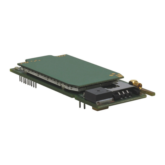
Specifications Product Description The Multi-Tech SocketModem GSM/GPRS is a complete, ready-to-integrate, embedded wireless modem. Designed for global use, it offers standards-based multi-band GSM/GPRS Class 10. The SocketModem GSM/GPRS is based on industry-standard open interfaces and utilizes the same form factor as the SocketModem, SocketModem IP, or SocketEthernet IP modules from Multi-Tech. -
Page 5: Product Features
UCS2 character set management *AT Commands - AT commands for this product are published in a separate document available on the Developer’s Kit system CD or from Multi-Tech. For a copy of this document, contact OEM Sales at oemsales@multitech.com or call (800) 972-2439. -
Page 6: Technical Specifications
Related Manuals AT commands for this product are published in a separate document available on the Developer’s Kit system CD or from Multi-Tech. Multi-Tech manuals and other resources are available on the Multi-Tech Web page at http://www.multitech.com. Additional Information... -
Page 7: Chapter 2 - Mechanical Specifications
Chapter 2 – Mechanical Specifications Chapter 2 – Mechanical Specifications Physical Dimensions SocketModem GSM/GPRS Mechanical Drawing... -
Page 8: Pin Configurations
Chapter 2 – Mechanical Specifications Pin Configurations The SocketModem GSM/GPRS uses a 13-pin interface. SocketModem Pins - Top View Pin Descriptions Signal Pin # Description Name Type -RESET I/O Reset. This signal is used to force a reset procedure by providing low level during at least 500µs. -
Page 9: Chapter 3 - Electrical Characteristics
Chapter 3 – Electrical Characteristics Chapter 3 – Electrical Characteristics Electrical characteristics for the 5V Serial SocketModem are presented in this chapter. I/O Electrical Characteristics 5 Vdc Characteristics (TA = -20° C to 55° C; VDD = 5 V ± 0.25 V) VDDMAX = 5.25 V Digital Inputs Input High... -
Page 10: Sim Interface Electrical Characteristics
Chapter 3 – Electrical Characteristics SIM Interface Electrical Characteristics SIM Interface Electrical Characteristics This information is repeated in the next chapter under the SIM Interface section. Parameter Conditions Unit = +/- 20 m A SIMDATA V 0.7xSIMVCC SIMDATA V = 1 mA 0.3xSIMVCC V SIMRST, Source current... -
Page 11: Chapter 4 - Socketmodem Interfaces
Chapter 4 - SocketModem Interfaces Chapter 4 – SocketModem Interfaces This chapter describes the SocketModem interfaces. · Flashing LED · SIM Interface · RF Interface Flashing LED The flashing LED signal is used to indicate the working mode of the SocketModem. LED and SocketModem Status Signal SocketModem Status... -
Page 12: Rf Interface
Chapter 4 - SocketModem Interfaces RF Interface The impedance is 50 Ohms nominal. RF Connector The RF connector is MMCX standard type. An antenna can be directly connected through the mating connector or using a small adapter. RF Performances RF performances are compliant with the ETSI recommendation 05.05 and 11.10. The main parameters are: Receiver Features ·... -
Page 13: Chapter 5 - Socketmodem Test Board
Chapter 5 – SocketModem Test Board Chapter 5 – SocketModem Test Board Serial Test/Demo Board Components... -
Page 14: Serial Test/Demo Board Block Diagram
Chapter 5 – SocketModem Test Board Serial Test/Demo Board Block Diagram Block Diagram for the SocketModem GSM/GPRS... -
Page 15: Chapter 6 - Application Considerations
The antenna should be isolated as much as possible from the digital circuitry including the interface signals. Multi-Tech recommends shielding the terminal. On terminals including the antenna, a poor shielding could dramatically affect the sensitivity of the terminal. Subsequently, the power emitted through the antenna could affect the application. -
Page 16: Appendix A - Safety Precautions & Regulatory Standards Compliance
Appendix A – Safety Precautions and Regulatory Standards Compliance Appendix A – Safety Precautions & Regulatory Standards Compliance Safety Precautions IMPORTANT! FOR THE EFFICIENT AND SAFE OPERATION OF YOUR GSM INTEGRATED MODEM READ THIS INFORMATION BEFORE USE. RF Safety General Your SocketModem is based on the GSM standard for cellular technology. -
Page 17: General Safety
Appendix A – Safety Precautions and Regulatory Standards Compliance General Safety Driving Check the laws and the regulations regarding the use of cellular devices in the area where you have to drive as you must comply with these laws and regulations. When using your modem while driving, please give full attention to driving. -
Page 18: General Safety Standards
§ 1.1307(b), § 2.1091 and § 2.1093 as appropriate. The Multi-Tech SocketModem is a GSM (PCS 1900) terminal which operates in the US licensed PCS frequency spectrum. The device transmits over the 1850-1910 MHz band and receives over the 1930- 1990 MHz Band. -
Page 19: Regulatory Standards Compliance
Appendix A – Safety Precautions and Regulatory Standards Compliance Regulatory Standards Compliance GSM compliance The SocketModem is in compliance with reference regulations: TBR 19, TBR 20, TBR 31, TBR 32. CE Label The Wireless SocketModem is CE compliant, which implies that the modem is in conformity with the European Community directives and it bears the CE label. -
Page 20: Appendix B - Sources For Peripheral Devices
Appendix B – Sources for Peripheral Devices Appendix B – Sources for Peripheral Devices GSM Antenna The integrated modem antenna connector is a MMCX connector. The MMCX connector incorporates a 'Snap On' latching action in order to make the connection easier with an excellent RF performance. An additional advantage is its small physical size, which is 50% of the standard MCX connector. -
Page 21: Appendix C - At Command List
Appendix C – AT Commands Appendix C – AT Command List For comprehensive information about AT Commands, please read the AT Commands Reference Manual. AT Command List General Commands +CGMI Manufacturer Identification +CGMM Request Model Identification +CGMR Request Revision Identification +CGSN Product Serial Number +CSCS... - Page 22 Appendix C – AT Commands AT Command List (continued) Security Commands +CPIN Enter PIN +CPIN2 Enter PIN2 +CPINC PIN Remaining Attempt Number +CLCK Facility Lock +CPWD Change Password Phone Book Commands +CPBS Select Phone Book Memory Storage +CPBR Read Phone Book Entries +CPBF Find Phone Book Entries +CPBW...
- Page 23 Appendix C – AT Commands AT Command List (continued) Supplementary Services Commands +CCFC Call Forwarding +CLCK Call Barring +CPWD Modify SS Password +CCWA Call Waiting +CLIR Calling Line Identification Restriction +CLIP Calling Line Identification Presentation +COLP Connected Line Identification Presentation +CAOC Advice Of Charge +CACM...
- Page 24 Appendix C – AT Commands AT Command List (continued) V24 - V25 Commands +IPR Fixed DTE Rate +ICF DTE-DCE Character Framing +IFC DTE-DCE Local Flow Control &C Set DCD Signal &D Set DTR Signal &S Set DSR Signal Back to Online Mode Result Code Suppression DCE Response Format Default Configuration...
-
Page 25: Appendix D - Acronyms And Abbreviations
Appendix D – Acronyms and Abbreviations Appendix D – Acronyms and Abbreviations ADC – Analog Digital Converter ASIC – Application Specific Integrated Circuit BCCH – Broadcast Control Channel CE – Communauté Européenne CLK – Clock CTS – Clear To send dB –... -
Page 26: Index
Index Index Advice Of Charge, 23 initial configuration, 15 aircraft and safety, 17 Instructions to OEMs, 18 analog, 25 Mechanical Drawing, 7 antenna, 12, 15, 16, 20 medical electronic equipment and safety, 17 antenna cable, 15 MMCX (Miniature Micro Connector), 12, 20 applications, 4 MO, 25 Commands, 21...
Need help?
Do you have a question about the SocketModem MTSMC-G-F1 and is the answer not in the manual?
Questions and answers