Table of Contents
Advertisement
Quick Links
Advertisement
Table of Contents

Related Manuals for Multi-Tech MTSMC-G2


Summary of Contents for Multi-Tech MTSMC-G2
- Page 1 SocketModem® GSM MTSME-G2 Hardware Guide for Developers...
- Page 2 Furthermore, Multi-Tech Systems, Inc. reserves the right to revise this publication and to make changes from time to time in the content hereof without obligation of Multi-Tech Systems, Inc. to notify any person or organization of such revisions or changes. See the Multi-Tech Web site for current revisions of documentation.
-
Page 3: Table Of Contents
TABLE OF CONTENTS ® ® Chapter 1 – SocketModem Cell (MTSMC-G2) & SocketModem iCell (MTSMC-G2-IP)...........4 Introduction ................................4 Product Build Options and Ordering Information ....................4 AT Commands Reference Guides...........................4 Technical Specifications ............................5 Electrical Characteristics ............................6 Power Consumption ..............................6 Mechanical Drawings – Basic Build ........................7 Mechanical Drawings –... -
Page 4: Chapter 1 - Socketmodem ® Cell (Mtsmc-G2) & Socketmodem ® Icell (Mtsmc-G2-Ip)
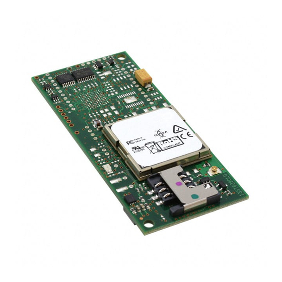
MTSMC-G2-IP) Introduction The MTSMC-G2 is a serial to wireless quad-band GPRS SocketModem. It is a complete, ready-to-integrate SocketModem that offers standards-based multi-band GSM/GPRS Class 10 performance. It is based on industry-standard open interfaces and utilizes Multi-Tech’s universal socket design. The SocketModem is available with the Multi-Tech's Universal IP™ stack to bring embedded Internet connectivity to any device. -
Page 5: Technical Specifications
Technical Specifications The MTSMC-G2 and MTSMC-G2-IP SocketModems meet the following specifications: Category Description Standards GPRS Class 10 Frequency Bands Quad-band GSM/EGPRS 850/900/1800/1900 MHz Serial/Data Speed Serial interface supports DTE speeds up to 921.6K IP interface supports DTE speeds at the fixed rate of 115.2 Packet data up to 85.6K bps... -
Page 6: Electrical Characteristics
0.080 0.135 0.280 1.250 without IP, too. Watts 0.382 0.664 1.358 Note: Current Peak = 1500mA maximum during Tx burst. * Multi-Tech Systems, Inc. recommends that the customer incorporate a 10% buffer into their power source when determining product load. -
Page 7: Mechanical Drawings - Basic Build
Mechanical Drawings – Basic Build... -
Page 8: Mechanical Drawings - Voice Build
Mechanical Drawings – Voice Build... -
Page 9: Mechanical Drawings - Ip Build
Mechanical Drawings – IP Build... -
Page 10: Application Notes
Application Notes Flashing LED Interface The flashing LED signal is used to indicate the working mode of the SocketModem. LEDs and SocketModem Status Signal SocketModem Status Download mode or switched OFF> Continuously lit Switched ON (not registered on the network) Flashing Switched ON (registered on the network) RF Performances... -
Page 11: Changing The Quad Band
Changing the Quad Band The SocketModem Cell and the SocketModem iCell both support quad band frequencies (850/1900/900/1800 MHz). In reality, these products operate like dual, dual-band devices. In other words, they can be configured for 850/1900 or 900/1800 MHz. They do not auto-seek the local area frequency. Build Options These wireless modems can be ordered with the default set to 850/1900 MHz or 900/1800 MHz. -
Page 12: Chapter 2 - The Antenna System
1W at 12.5% duty cycle cycle cycle cycle Coax Cable An optional 6” antenna cable (SMA Jack to UFL Plug) can be ordered from Multi-Tech Systems, Inc. Part Number Description CASMA-UFL-1 SMA to UFL COAX RF 6 inch cable (Single Pack) CASMA-UFL-10... -
Page 13: Chapter 3 - Design Considerations
Chapter 3 – Design Considerations Noise Suppression Design Considerations Engineering noise-suppression practices must be adhered to when designing a printed circuit board (PCB) containing the SocketModem module. Suppression of noise is essential to the proper operation and performance of the modem itself and for surrounding equipment. Two aspects of noise in an OEM board design containing the SocketModem must be considered: onboard/off- board generated noise that can affect digital signal processing. -
Page 14: Electrostatic Discharge Control
Multi-Tech Systems, Inc. strives to follow all of these recommendations. Input protection circuitry has been incorporated into the Multi-Tech devices to minimize the effect of this static buildup, proper precautions should be taken to avoid exposure to electrostatic discharge during handling. -
Page 15: Chapter 4 - Safety Notices And Warnings
Chapter 4 – Safety Notices and Warnings Note to OEMs: The following safety statements may be used in the documentation of your final product applications. Telecom Safety Warning Never install telephone wiring during a lightning storm. Never install a telephone jack in wet locations unless the jack is specifically designed for wet locations. This product is to be used with UL and cUL listed computers. -
Page 16: Upgrading Firmware
Multi-Tech's Flash Wizard can be downloaded from Multi-Tech’s FTP site and is available on CD. Use this Flash Wizard for upgrading your firmware. -
Page 17: Wireless Approvals And Labeling Requirements
Wireless Approvals and Labeling Requirements Wireless Approvals (GSM, CDMA) The Multi-Tech SocketModem is Industry and/or Carrier Approved as an End Product modem. In most cases, when integrated and used with an antenna system that was part of the Multi-Tech modem certification, no additional... - Page 18 The Following Is an Example of a CDMA Label: Multi-Tech Model Identification Multi-Tech Ordering Part Number ESN: Electronic Serial Number in Hexadecimal Format and Decimal Format • Other Information the Wireless Carrier Asks You to Provide: For CDMA SocketModems: The modem's 8-character ESN (Electronic Serial Number) number printed next to the barcode on the modem.
-
Page 19: Regulatory Compliance Statements
Regulatory Compliance Statements EMC, Safety, and R&TTE Directive Compliance The CE mark is affixed to this product to confirm compliance with the following European Community Directives: Council Directive 2004/108/EC of 15 December 2004 on the approximation of the laws of Member States relating to electromagnetic compatibility;... - Page 20 New Zealand Telecom Warning Notice The grant of a Telepermit for any item of terminal equipment indicates only that Telecom has accepted that the item complies with minimum conditions for connection to its network. It indicates no endorsement of the product by Telecom, nor does it provide any sort of warranty.
- Page 21 Other The above country-specific examples do not cover all countries with specific regulations; they are included to show you how each country may differ. If you have trouble determining your own country's requirements, check with Multi-Tech's Technical Support for assistance.
-
Page 22: Waste Electrical And Electronic Equipment Statement
Substances) complements the WEEE Directive by banning the presence of specific hazardous substances in the products at the design phase. The WEEE Directive covers all Multi-Tech products imported into the EU as of August 13, 2005. EU-based manufacturers, distributors, retailers and importers are obliged to finance the costs of recovery from municipal collection points, reuse, and recycling of specified percentages per the WEEE requirements. -
Page 23: Restriction Of The Use Of Hazardous Substances (Rohs)
Certificate of Compliance 2002/95/EC Multi-Tech Systems Inc. confirms that its embedded products now comply with the chemical concentration limitations set forth in the directive 2002/95/EC of the European Parliament (Restriction Of the use of certain Hazardous Substances in electrical and electronic equipment - RoHS) These Multi-Tech Systems, Inc. -
Page 24: Information On Hs/Ts Substances According To Chinese Standards In English
Information Products (EIP) # 39, also known as China RoHS, the following information is provided regarding the names and concentration levels of Toxic Substances (TS) or Hazardous Substances (HS) which may be contained in Multi-Tech Systems Inc. products relative to the EIP standards set by China’s Ministry of Information Industry (MII). -
Page 25: Information On Hs/Ts Substances According To Chinese Standards In Chinese
Information on HS/TS Substances According to Chinese Standards in Chinese 依照中国标准的有毒有害物质信息 根据中华人民共和国信息产业部 (MII) 制定的电子信息产品 (EIP) 标准-中华人民共和国《电子信息产品污染控制管理办法》(第 39 号),也称作中国 RoHS,下表列出了 Multi-Tech Systems, Inc. 产品中可能含有的有毒物质 (TS) 或有害物质 (HS) 的名称及含量水平方面的信息。 有害/有毒物质/元素 铅 汞 镉 六价铬 多溴联苯 多溴二苯醚 成分名称 (PB) (Hg) (CD) (CR6+) (PBB) (PBDE) 印刷电路板... -
Page 26: Chapter 5 - Socketmodem Developer Board
Chapter 5 – SocketModem Developer Board SocketModem Developer Board This developer board drawing shows the major board components for all SocketModems. Comment [DAR7]: C:\Universal_So cketModem \ Graphics_ETC_Rev_I \ Board Revision B Board_B_Schematics \ See the next page for description of Board Components SchematicsfromJohnM \ Board_B_for_Universal_260b0_forRe v J jumper fixed.png... -
Page 27: Board Components
SocketModem. If this jumper is set incorrectly, damage to the SocketModem and/or the Test/Demo card could result. Caution – Use only the provided Multi-Tech Systems, Inc. transformer with the Test/Demo board. Use of any other power source will void the warranty and will likely damage the Test/Demo board and the SocketModem. -
Page 28: Socketmodem Developer Board Block Diagram
SocketModem Developer Board Block Diagram Comment [DAR8]: Block Diagram 2008.png... -
Page 29: Developer Board Schematics
Developer Board Schematics Comment [DAR9]: Schematics Board Revision B Board B page 2 Scan0576_000.jpg did not change to gif – file was already small... -
Page 30: Developer Board Schematics
Comment [DAR10]: Schematics Board B page 3 Developer Board Schematics Scan0577_000grayscale50percent.gif (changed from jpg to make the file size smaller 8/5/09) Board Revision B... - Page 31 Developer Board Schematics Comment [DAR11]: Schematics Board B page 4 Scan0575_000grayscale.gif (was jpg – now a gif for a smaller file 9/5/09) Board Revision B...
-
Page 32: Developer Board Schematics
Comment [DAR12]: Schematics Developer Board Schematics Board B page 5 Scan0574_000grayscale50percent.gif (was jpg but file was too large. Now gif 8/5/09) Board Revision B... -
Page 33: Developer Board Schematics
Developer Board Schematics Comment [DAR13]: Schematics Board B page 6 Scan0573_000.jpg did not change to gif – file was Board Revision B already small...
Need help?
Do you have a question about the MTSMC-G2 and is the answer not in the manual?
Questions and answers