Table of Contents
Advertisement
Advertisement
Table of Contents

Related Manuals for Jumpking OR1413B6A1


Summary of Contents for Jumpking OR1413B6A1
- Page 3 ® CONTENTS IMPORTANT PRECAUTIONS ......4 WARNING LABEL PLACEMENT ......6 BEFORE YOU BEGIN ....... . 7 TRAMPOLINE/ENCLOSURE SAFETY INFORMATION ..
- Page 6 Inspect before use and replace any worn, defective or missing parts. Avoid bouncing when tired. OR1413B6A1 While keeping the head erect, focus eyes on the trampoline toward the perimeter. OR1413B6A1 The placard shown at the below must be attached to the trampoline enclosure by the owner (see assembly step 15 on page 20).
- Page 7 1-877-927-8777,...
- Page 11 sharply spot.
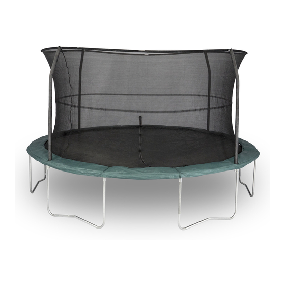
- Page 15 Lay out all of the parts in groups : 4 Toprails with T-connector w/ round slot (2) 8 Toprails with T-connector (1) T-connector+ 12 Leg extensions (5) Welded tube(4) 6 " W" shaped legs (6) Connect Toprail(2) with t-connector w/slot(4) to toprail(1) with t-connector(3). Then connect another toprail with t-connector to finish 1 section.
- Page 16 3. Lay the Bed (7) on the ground inside of the assembled frame. Make sure that the two warn- ing decals (not shown) are on top of the Bed. Note: There are V-rings around the edge of the Bed (7) and holes around the top of the frame. During this step, you will attach the Bed to the frame using the included Springs (9) for holes on top of frame and for holes on bottom of frame...
- Page 17 4. Lay the Frame Pad (8) on the frame. Double D-rings on the middle of pad should be fixed exactly on the right of each T-connector of frame. Do not use the trampoline without the Frame Pad (8), which is designed to reduce the Webbing likelihood of injury to the user from coming in con- tact with the trampoline frame.
- Page 18 6. Using the included plastic tie, attach the Safety Placard (10) to the frame near the point where jumpers will climb onto and off the trampoline. The trampoline is now fully assembled. Make sure that all parts are securely attached. Familiarize yourself and all users of the tram- poline with the safety precautions, use and instructional materials, and care and mainte-...
- Page 19 9. Lay out Top G3 Pole (14), joint each section 6 Sections Per Line Connector to a straight line as shown. Top G3 Pole (14) Assemble the remaining Top G3 Pole (14) in the same way. Spread out G3 Pole and Joint each section to one straight line.
- Page 20 11. Note: During steps 12 and 13, you will “sew” the lower edge of the Netting(16) to the V-rings on the bed using the Cords(18). Locate the V-ring closest to the door. Thread one end of a Cord(18) through the lower edge of the Netting(16) above the V-ring and then thread the Cord through the V-ring.
- Page 21 Stake It is possible for the trampoline/enclosure be blown about by high wind. If you anticipate high winds, the trampoline/enclosure should be moved to a sheltered location, disassembled, or tied down to the ground with ropes and stakes (not included). At least three ropes and three stakes should be used.
- Page 22 Top Enclosure pole Top Tube(With T-connector) Top Tube(With T-connector + Welded Self-tapping screw tube) G3 Pole (Black) T-Connector Hemisphere Cap ( This part has been atta- T-Connector + Welded tube ched to the top of the Top Tube (12).) Leg Extension Netting with attached Hardware Leg Center Foam Sleeve...
- Page 23 Top Tube with T-connector Top Tube with T-connector T-connector Note: This part may be pre-assembled onto key#1 T-connector + Welded tube Note: This part may be pre-assembled onto key#2 Leg Extension Leg Center Stitched Bed with V-ring Frame Pad Springs Safety Placard Spring pulling tool...
- Page 24 Safety placard Bottom enclosure pole Top enclosure pole Self-tapping screw G3 pole Hemisphere Cap (Pre-assembled to key#12) Netting with attached hardware Foam sleeves Cord...
Need help?
Do you have a question about the OR1413B6A1 and is the answer not in the manual?
Questions and answers