Table of Contents
Advertisement
Quick Links
Advertisement
Table of Contents

Subscribe to Our Youtube Channel
Related Manuals for Ruijie RG-IS2712G


Summary of Contents for Ruijie RG-IS2712G
- Page 1 RG-IS2700G Series Switch Hardware Installation and Reference Guide V1.12...
- Page 2 This document is provided “as is”. The contents of this document are subject to change without any notice. Please obtain the latest information through the Ruijie Networks website. Ruijie Networks endeavors to ensure content accuracy and will not shoulder any responsibility for losses and damages caused due to content omissions, inaccuracies or errors.
- Page 3 It is intended for the users who have some experience in installing and maintaining network hardware. At the same time, it is assumed that the users are already familiar with the related terms and concepts. Obtaining Technical Assistance Ruijie Networks Website: http://www.ruijienetworks.com/ Service Email: service_rj@ruijienetworks.com ...
-
Page 4: Product Overview
RG-IS2700G Series Switch Hardware Installation and Reference Guide 1 Product Overview The RG-IS2700G series switches are the next generation layer-2 switches launched by Ruijie Networks. Integrated with high performance, high security and multiple services, the RG-IS2700G series switches are mainly deployed in the... - Page 5 RG-IS2700G Series Switch Hardware Installation and Reference Guide refer to AppendixB for BIDI optic module details. SFP Port Supporting 1000Base-X; Supporting 2.5Gbps bandwidth, and VSU deployment Power Supply AC input: Rated voltage range: 100VAC to 240VAC Maximum voltage range: 85VAC to 265VAC Frequency: 50Hz to 60Hz Rated current: 0.4A ...
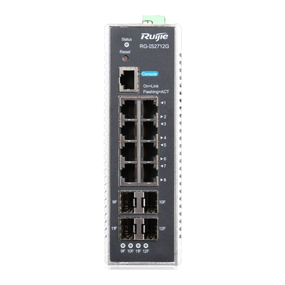
- Page 6 160 mm x 115 mm x 52 mm Weight 1 kg RG-IS2712G switch is a class A product. In a domestic environment, this product may cause radio interference in which case the user may be required to take adequate measures. Product Appearance The front panel of the RG-IS2712G Ethernet switch provides eight 10/100/1000Base-T Ethernet ports, four Gigabit SFP fiber ports and one Console port.
- Page 7 RG-IS2700G Series Switch Hardware Installation and Reference Guide Front Panel Figure 1-2 RG-IS2712G Front Panel...
- Page 8 7. 1000Base-X SFP port indicator 4. 10/100/1000Base-T adaptive Ethernet 8. Power interface port indicator Side panel Figure 1-3 RG-IS2712G Side Panel 1. 6-pin AC power connector 2. Grounding pole Note 3. Warning Label for high temperature and electric shock Back panel...
- Page 9 MAC address of the device DIN slot Tips for software preinstallation Power Supply The RG-IS2712G switch adopts the AC power input. AC input: Rated voltage range: 100 VAC to 240 VAC Maximum voltage range: 85 VAC to 265 VAC...
- Page 10 Heat Dissipation The RG-IS2712G switch is designed with no fans. To ensure good dissipation, sufficient ventilation space (10 cm distance from both sides and the back panel of the chassis) should be reserved to avoid the air inlet of the chassis from being blocked;...
- Page 11 RG-IS2700G Series Switch Hardware Installation and Reference Guide GE-SFP-LX20-SM1310-BIDI GE-SFP-LX20-SM1550-BIDI GE-SFP-LH40-SM1310-BIDI GE-SFP-LH40-SM1550-BIDI 1000Base-T: Mini-GBIC-GT SFP module, supporting 2.5Gbps bandwidth and VSU deployment: GE-SFP-STACK1.6M The supported module type may change at any time. Contact us for the detailed change information. BIDI optic modules must be used in pairs.
- Page 12 RG-IS2700G Series Switch Hardware Installation and Reference Guide IEC/EN 61000-4-4 EFT Power Cable 2 kV Data Cable 1 kV IEC/EN 61000-4-6 CS 15kHz-80 MHz IEC/EN 61000-4-8 PFMF 50Hz 30A/m IEC/EN 61000-4-5 Surge Power cable, L/N Power cable, L-PE/N-PE Data cable IEC/EN 61000-4-11 DIP AC220V CLASS 3...
- Page 13 RG-IS2700G Series Switch Hardware Installation and Reference Guide Figure 1-6 RG-IS2706G Front Panel Note 1. Switch status indicator 5. 10/100/1000Base-T adaptive Ethernet port 2. Reset button 6. 1000Base-X SFP port/2.5 G stack port 3. Console port 7. 1000Base-X SFP port indicator 4.
- Page 14 RG-IS2700G Series Switch Hardware Installation and Reference Guide Note 1. 6-pin AC power connector 2. Grounding pole 3. Warning Label for high temperature and electric shock Back panel Figure 1-8 RG-IS2706G Back Panel...
- Page 15 RG-IS2700G Series Switch Hardware Installation and Reference Guide Note Product information label 10. Network access license of the device Device bar code 11. MAC address of the device DIN slot 12. Tips for software preinstallation Power Supply The RG-IS2706G adopts the AC power input. ...
- Page 16 No link, or port was administratively shut down. 5F, 6F Solid green Link present. Blinking green Activity. The port is receiving or sending data. 1.3 RG-IS2712G-DC Technical Specifications Table 1-4 Technical specifications of the RG-IS2712G-DC Switches Model RG-IS2712G-DC Module Type Gigabit Ethernet: MINI-GBIC-SX-MM850 MINI-GBIC-LX-SM1310...
- Page 17 RG-IS2700G Series Switch Hardware Installation and Reference Guide GE-SFP-LH40-SM1310-BIDI GE-SFP-LH40-SM1550-BIDI 1000Base-T: Mini-GBIC-GT SFP module, supporting 2.5Gbps bandwidth and VSU deployment: GE-SFP-STACK1.6M The supported module type may change at any time. Contact us for the detailed change information. BIDI optic modules must be used in pairs. If GE-SFP-LX20-SM1310-BIDI is used at one end, then GE-SFP-LX20-SM1550-BIDI must be applied to the other end.
- Page 18 160 mm x 115 mm x 52 mm Weight 1 kg RG-IS2712G-DC switch is a class A product. In a domestic environment, this product may cause radio interference in which case the user may be required to take adequate measures. Product Appearance The front panel of the RG-IS2712G-DC Ethernet switch provides eight 10/100/1000Base-T Ethernet ports, four Gigabit SFP fiber ports and one Console port.
- Page 19 1. Switch status indicator 5. 10/100/1000Base-T adaptive Ethernet port 2. Reset button 6. 1000Base-X SFP port/2.5 G stack port 3. Console port 7. 1000Base-X SFP port indicator 4. 10/100/1000Base-T adaptive Ethernet 8. Power interface port indicator Side panel Figure 1-11 RG-IS2712G-DC Side Panel...
- Page 20 RG-IS2700G Series Switch Hardware Installation and Reference Guide Note 1. Six-pin power connector 2. Grounding pole 3. Warning Label for high temperature and electric shock Back panel Figure 1-12 RG-IS2712G-DC Back Panel...
- Page 21 MAC address of the device DIN slot Tips for software preinstallation Power Supply The RG-IS2712G-DC switch adopts the DC power input. Two power supplies are supported for 1+1 power redundancy. DC input: Rated voltage: 24VDC, 48VDC Maximum voltage range: 18VDC to 72VDC Maximum current: 0.1A...
- Page 22 RG-IS2700G Series Switch Hardware Installation and Reference Guide LED Indicators Indicator Faceplate Status Meaning Marker Status indicator Status The switch is not powered on. Blinking green The switch is being initialized. If the blinking persists, however, it indicates that an abnormality occurs.
-
Page 23: Preparation Before Installation
RG-IS2700G Series Switch Hardware Installation and Reference Guide 2 Preparation before Installation 2.1 Safety Suggestions To avoid personal injury and equipment damage, please carefully read the safety suggestions before you install the RG-IS2700G series. The following safety suggestions do not cover all possible dangers. 2.1.1 Safety Precautions for Installing the System ... -
Page 24: Static Discharge Damage Prevention
RG-IS2700G Series Switch Hardware Installation and Reference Guide Direct or indirect touch through a wet object on high-voltage and mains supply may bring a fatal danger. 2.1.4 Static Discharge Damage Prevention To prevent damage from static electricity, pay attention to the following: ... -
Page 25: Cleanness Requirements
RG-IS2700G Series Switch Hardware Installation and Reference Guide In an environment with high temperature, the equipment is subject to even greater harm, as its performance may degrade significantly and its useful life may be shortened in the case of long-term exposure that expedites the aging process. - Page 26 RG-IS2700G Series Switch Hardware Installation and Reference Guide The switch should be located at places free from large power radio launch pad, radar launch pad, and high-frequency large-current devices. If necessary, electromagnetic shielding should be adopted. For example, use interface cables to shield cables. 2.3 System Grounding Requirements A good grounding system is the basis for the stable and reliable operation of the RG-IS2700G series.
- Page 27 RG-IS2700G Series Switch Hardware Installation and Reference Guide 2.4 Lightning Resistance Considerations When the AC power cable is imported outdoors and directly connected to the power port of the switch, lightning line bank should be adopted to prevent the switch from being hit by lightning shocks. The lightning line bank can be fixed on the cabinet, work station, or the equipment room's wall through line buckles and screws.
-
Page 28: Installation Tools
RG-IS2700G Series Switch Hardware Installation and Reference Guide There are two types of electromagnetic interferences: radiated interference and conducted interference, depending on the type of the transmission path. When the energy, often RF energy, from a component arrives at a sensitive component via the space, the energy is known as radiated interference. -
Page 29: Product Installation
RG-IS2700G Series Switch Hardware Installation and Reference Guide 3 Product Installation Please ensure that you have carefully read the Chapter of Preparation before Installation. Make sure that the requirements set forth in Chapter 2 have been met. 3.1 Installation Procedure 3.2 Confirmations before Installation Before installation, please confirm the following points: ... -
Page 30: Mounting The Switch On A Din Rail
RG-IS2700G Series Switch Hardware Installation and Reference Guide Connect the power cables of different colors to the corresponding grounding posts. Ensure that the connected power cables have sound contact. Do not place heavy items on the switch. ... - Page 31 RG-IS2700G Series Switch Hardware Installation and Reference Guide Figure 3-4 3.3.3 Mounting the Switch with a Vertical Bracket Remove the four screws from the rear panel of the switch. Figure 3-5...
- Page 32 RG-IS2700G Series Switch Hardware Installation and Reference Guide Attach the vertical bracket to the rear panel of the switch. Align the mounting holes on the vertical bracket to the screw holes on the rear panel of the switch and tighten the mounting screws. Keep the round screw holes on the vertical bracket downward. Figure 3-6 Mark the location of round screw mounting holes, then remove the switch.
- Page 33 RG-IS2700G Series Switch Hardware Installation and Reference Guide 3.3.4 Connecting Power Cord to Power Connector 3.3.4.1 RG-IS2706G and RG-IS2712G Insert the power cord into the 6-pin connector, as shown in Figure 3-8. 1 indicates the protective earth (PE) ground wire, which is green with yellow strip.
- Page 34 RG-IS2700G Series Switch Hardware Installation and Reference Guide Figure 3-10 3.3.4.2 RG-IS2712G-DC Two two-pin wires are needed. Insert the power cords into the 6-pin connector, as shown in Figure 3-11. V1+ and V2+ (red wires) indicate the positive poles of power supplies while V1- and V2- (black wires) indicate the negative poles.
-
Page 35: Checking After Installation
RG-IS2700G Series Switch Hardware Installation and Reference Guide Turn bolts on the connector clockwise and plug the connector into the switch. The RG-IS2712G-DC switch adopts the DC power input. Two power supplies are supported for 1+1 power redundancy. 3.4 Checking after Installation Before checking the installation, switch off the power supply so as to avoid any personal injury or damage to the component due to connection errors. -
Page 36: System Debugging
RG-IS2700G Series Switch Hardware Installation and Reference Guide 4 System Debugging 4.1 Establishing the Configuration Environment Establishing the Configuration Environment Connect the PC to the console port of the switch through the console cable, as shown in Figure 4-1. Figure 4-1 Schematic diagram of the configuration environment 4.1.1 Connecting the Console Cable Step 1: Connect one end of the DB-9 jack of the console cable to the serial port of the PC. - Page 37 RG-IS2700G Series Switch Hardware Installation and Reference Guide In the Connectivity Note window, type the name of the new connection and click OK. A window appears as shown in Figure 4-3. In the Connect Using field, select the serial port you want to use. Figure 4-3 After selecting the serial port, click OK.
- Page 38 RG-IS2700G Series Switch Hardware Installation and Reference Guide After setting the serial port parameters, click OK. The Hyperterminal window appears. 4.2 Power-on Startup Checking before Power-on The switch is fully grounded. The power cable is correctly connected. The power supply voltage complies with the requirement of the switch.
-
Page 39: Maintenance And Troubleshooting
5.1 General Troubleshooting Procedure 5.2 Troubleshooting Common Faults Symptom Possible Causes Solution Forgetting the management Please contact Ruijie Networks interface login password Customer Service Department for technical support. The status indicator is not on after The power supply module does not Check whether the power socket the switch is started. - Page 40 RG-IS2700G Series Switch Hardware Installation and Reference Guide Symptom Possible Causes Solution refrigeration effect. The serial port console has no The serial port connected to the switch Change the serial port opened by output or outputs illegible does not match that opened by the the configuration software to be characters.
-
Page 41: Appendix A Connectors And Connection Media
RG-IS2700G Series Switch Hardware Installation and Reference Guide 6 Appendix A Connectors and Connection Media 1000BASE-T/100BASE-TX/10BASE-T Ports The 1000BASE-T/100BASE-TX/10BASE-T is a port that supports adaptation of three rates, and automatic MDI/MDIX Crossover at these three rates. The 1000BASE-T complies with IEEE 802.3ab, and uses the cable of 100-ohm Category-5 or Supper Category-5 UTP or STP, which can be up to 100 m. - Page 42 RG-IS2700G Series Switch Hardware Installation and Reference Guide Fiber-Optic Connection For fiber ports, select single-mode or multimode fibers for connection according to the fiber module connected. The connection schematic diagram is shown in 0: Figure A-4 Schematic diagram for fiber connection...
-
Page 43: Appendix B Mini-Gbic Modules
RG-IS2700G Series Switch Hardware Installation and Reference Guide 7 Appendix B Mini-GBIC Modules We provide appropriate 1000M SFP modules (Mini-GBIC modules) for different module interfaces of the switch. You can select the SFP module as needed. The following models and technical specifications of some 1000M SFP modules are listed for your reference. Models and Technical Specifications of the Mini-GBIC (SFP) Module Table B-1 Models and Technical Specifications of the SFP Module Transmit... - Page 44 RG-IS2700G Series Switch Hardware Installation and Reference Guide The optic module is a later emitter. Please do not look at the light source to avoid hurting your eyes. Please cover the optic module with a dust shield when it is not in use to keep it clean. Table B-2 Model and Technical Specification of 1000Base-T Copper SFP Module Copper Wire...
Need help?
Do you have a question about the RG-IS2712G and is the answer not in the manual?
Questions and answers