
Related Manuals for Lumel N10


Summary of Contents for Lumel N10
- Page 1 POWER NETWORK PARAMETER ANALYSER SERVICE MANUAL CD Automation UK Ltd Tel: +44 (0)1323 811100 Email: info@cdautomation.co.uk Web: www.cdautomation.co.uk/N10...
-
Page 2: Table Of Contents
3.1. FITTING................6 3.2. EXTERNAL CONNECTION DIAGRAMS........7 4. PROGRAMMING ..............12 4.1. FACEPLATE DESCRIPTION...........12 4.2. N10 OPERATING MODES............14 4.2.1 MEASURING MODE............15 4.2.1.1. Measurement of voltage and current harmonics.......16 4.2.2. TIME SETTING MODE - t.............17 4.2.3. PARAMETER CONFIGURATION MODE - S......18 4.2.4. -
Page 3: Service Manual
1. APPLICATION The.N10.type.meter.is.a.programmable.digital.instrument.destined. to.measure.parameters.in.three-phase,.3.or.4-wire.power.networks,. in.symmetric.and.asymmetric.systems.with.the.simultaneous.display. of.measured.quantities.and.the.digital.transmission.of.their.values. and.their.conversion.into.an.analog.standard.signal. This.meter.enables.the.control.and.optimization.of.power.electronic. devices,.systems.and.industrial.installations..It.ensures.the.measure- ment.of:.RMS.voltage.and.current,.active.power.and.energy,.reactive. power.and.energy,.power.factors,.frequency,.15-minutes.active.mean. powers..Voltages.and.currents.are.multiplied.by.given.voltage.and. current.ratios.of.voltage.and.current.measuring.transformers..Power. and.energy.indications.take.into.consideration.values.of.programmed. ratios..This.meter.indicates.additionally.the.actual.time..The.value.of. each.measured.quantity.can.be.transmitted.to.the.superordinated. system.through.the.RS-485.interface..One.of.the.chosen.quantity.can. be.additionally.transmitted.by.means.of.a.standard.current.signal,. three.relays.outputs.can.be.used.to.signalize.exceedings.of.chosen. quantities,. a. pulse. output. to. control. energy. counters. with. pulse. inputs,.and.a.pulse.input.to.check.counters.having.pulse.outputs.. Measurements.are.carried.out.by.the.sampling.method.of.voltage. and.current.signals..The.meter.is.adapted.to.be.fixed.into.a.pannel. by.means.of.holders. 2. METER SET The.set.includes: -.N10.type.meter. 1.pc. -.service.manual. -
Page 4: Installation
3. INSTALLATION 3.1. Fitting way The. meter. is. adapted. to. be. mounted. by. means. of. holders. accor. ding.fig.1. The.meter.housing.is.made.of.a.sell-extinguishing.plastics. Housing.dimensions.are.144.x.144.x.77mm..At.the.outside.of.the. meter.there.are.screwed.terminal.strips.which.enable.the.connection. up.to.2.5.mm .external.leads. Fig.1. Overall dimensions and fitting way of the N10 meter. -
Page 5: External Connection Diagrams
3.2. External connection diagrams Direct measurement in a 3-phase network Half-intermediate measurement in a 3-phase network... - Page 6 Intermediate measurement using 2-current transformers and 2 or 3 voltage transformers in a 3-phase network Fig. 2. Meter connection diagrams in a three-phase network...
- Page 7 Direct measurement in a 4-phase network Half-intermediate measurement in a 4-wire network...
- Page 8 Intermediate measurement using 2-current transformers and 2 or 3 voltage transformers in a 3-phase network Fig. 3. Meter connection diagrams in a four-wire network...
- Page 9 Fig. 4. Connecting way of N10 meters with an RS-485 interface.
-
Page 10: Programming
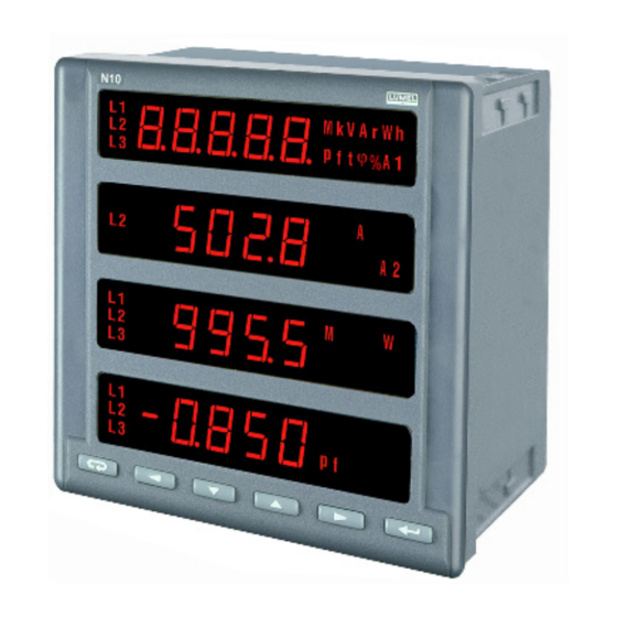
4.1. Faceplate description Fig. 5. View of the N10 meter faceplate The. N10. meter. has. 6. keys,. four. 5-digits. display. sections. and. il- luminated. symbols. and. parameter. units.. Values. of. measured. . parameters. are. shown. on. active. pages. selected. by. successive. . - Page 11 Table 1 ENTER.acceptance.key Right.displacement.key Value.increase.key. Value.decrease.key Left.displacement.key ESC.resignation.key The assignment of individual keys is as follows: .Key It.is.destined.to.accept.the.introduced.value.during.the.programma- tion..It.enables.the.change.of.pages.in.the.measuring.mode. .Keys They.are.destined.to.change.the.digit.value.on.the.decimal.posi- tion.during.the.programmation..They.enable.the.display.of.suitably. minimal.and.maximal.values. .Keys They. allow. the. cursor. displacement. to. successive. decimal. posi- tions.during.the.programmation.and.enable.the.change.of.display. luminosity. .Key This.key.enables.in.anytime.the.resignation.of.carried.out.operations.. It.cancels.alarms.in.measuring.mode.
-
Page 12: N10 Operating Modes
4.2. N10 operating modes The.N10.meter.has.5.operating.modes.represented.. on.the.table.2. Table 2 MODE CALLING.OUT. NAME OUTPUT INPUT SYMBOL Through.input.to.. Understood Measuring another.mode in.SETUP. .or. .after.the. Time.setting procedure last.parameter in.SETUP. Page.. .or. .after.the. procedure configuration last.parameter Parameter.. in.SETUP. .or. .after.the. configuration procedure last.parameter Alarm.. in.SETUP. -
Page 13: Measuring Mode
Choose.by.means.of. .keys.the.appropriate.mode..The. active.mode.t,.P,.S.or.A.is.signalled.by.the.flashing.of.the.suitable. symbol..Accept.the.chosen.mode.by.the. .key. The.return.from.other.modes.into.the.measuring.mode.is.carried. out.by.means.of.the. .or. .key: -.after.the.last.parameter.(in.t,.S.and.A.modes), -.after.the.last.page.(in.the.P.mode). 4.2.1. Measuring mode Values.of.different.quantities.are.displayed.acc..programmed.pages. by.the.manufacturer.or.configurated.by.the.user.in.the.P.mode. The. change. of. page. is. realized. by. pressing. the. . Key.. The. sequence.of.displayed.pages.is.proceeded.acc..the.table.formed. in.the.P.mode. The.monitoring.of.maximal.or.minimal.values.is.realized.when.press- ing.respectively.the. .or. .key..The.cancellation.of.maximal. or.minimal.values.is.realized.when.pressing.the. .key.during. the.monitoring.of.these.values,.i.e..at.first.the. .key. must.be.pressed.and.after.the. .key. Alarms. -
Page 14: Measurement Of Voltage And Current Harmonics
4.2.1.1. Measurement of voltages and current harmonics The.selection.of.harmonics.is.made.by.pressing. .keys. for.reviewing.current.harmonic,.or.by. .keys.for.review- ing.voltage.harmonics. The.selected.U1,U2,U3.or.I1,I2,.I3.quantity.is.signalled.by.the.flash- ing.of.the.suitable.digit..One.must.choose.by.the. .or. key.the.required.quantity.and.press.the. .key..The.following. quantities.will.be.displayed: Where:..w-n..-.chosen.quantity,.e.g..U-1....n-n..-.harmonic.number ....xxx.x.-.value.of.the.n-th.harmonic.. The.harmonic.number.up.to.the.25th.harmonic.can.be.changed.by. means. of. . or. . keys.. The. active. position. is. signalled. by.the.cursor..One.can.return.to.display.the.selection.of.reviewed. harmonics.by.pressing.the. .key..A.successive.pressure.of.the. .key.means.the.return.to.the.measuring.mode. For. wrong. THD. indications,. successive. harmonic. values. will. not. be.displayed. -
Page 15: Time Setting Mode - T
NOTICE:. Indications.appear.when.the.parameter.22.will.be.switch.on.in.the. SETUP.mode,.i.e..the.selection.of.the.harmonic.measurement.and. the.assumptions.concerning.the.measurement.will.be.fulfilled. 4.2.2. Setting time mode - t After.the.entry.into.the.SETUP.procedure.one.must.choose.the.mode. t.by.pressing.the. .or. .key.and.the. .key..Following. values.will.be.displayed: Where:..yyyy..-.year....mm..-.month ....dd.-.day.. By.means.of. .keys.required.values.can. be.set,.i.e..the.position.of.the.decimal.digit.can.be.choosen.by.the. .or. .key,.the.digit.value.by.the. .or. .key..The. cursor.signalizes.the.active.position..The.set.value.can.be.accepted. by.the. .key.or.cancelled.by.the. .key.and.comes.back. into.the.measuring.mode. .causes.the.arrangement.on.the.successive.parameter. .after.dd.(day),.causes.the.transition.to.hours.and.minutes. settings. Where:..hh..-.hours....mm..-.minutes ....ss.-.secondes. -
Page 16: Parameter Configuration Mode - S
The.setting.of.hours.and.minutes.is.similar.to.the.setting.of.the.year,. month.and.day. .after.min.(minutes),.causes.the.memorization.of.set.values. and.the.exit.from.the.mode.t. The.seconde.counter.is.not.be.set.but.it.is.zeroed.when.accepting. minutes..This.means.that.in.order.to.obtain.an.accurate.timer.set- ting.one.must.wait.till.a.full.minute.and.then.press.the. .key. (ENTER). 4.2.3. Parameter configuration mode - S This. mode. is. destined. to. set. meter. parameters,. input. and. output. signal.values..The.entry.into.the.parameter.configuration.mode.is. protected.by.the.access.code.if.an.access.code.different.from.zero. had.been.introduced. In.the.case.of.0000.code,.password.inquiry.is.omitted..If.the.access. code. is. different. from. zero,. there. is. the. possibility. of. parameter. reviewing,.but.changes.are.locked. - Page 17 Table.3 Quantity.code.acc.. Quantity.on.the.pulse. Po_n 0,.35...37 output table.5 Pulse.number/. Constans.of.the.pulse. Po_c 0...9999 1000 1kWh,kVar,kVAhmax. output 2..pulses/sec. Quantity.on.the.pulse. Quantity.code.acc.. PI_n 0,.38...40 input table.5 Constant.of.the.ex- Pulse.number/ PI_c 1...9999 1000 ternal.energy.counter. 1kWh,kVarh,kVAh (pulse.input) Cancellation.of.the.ex- ternal.energy.counter. PI_0 (counter.of.the.pulse. input) Cancellation.of.the.ac- EnP0 tive.energy.counter Cancellation.of.the.re- Enq0 active.energy.counter Cancellation.of.the.ap- EnS0 parent.energy.counter...
-
Page 18: Alarm Configuration Mode - A
Notations: N.-.lack.of.parity.(no.parity),. E.-.bit.checking.the.even.parity, O.-.bit.checking.the.odd.parity. The.entry.into.the.procedure.causes.the.setting.on.the.parameter.1. or.2.if.the.access.code.is.equal.0000..We.adjust.required.values.by. means.of. .keys,.i.e..one.can.choose.the. position.of.the.decimal.digit.by.pressing.the. .or. .key,.the. digit.value.by.pressing.the. .or. .key..The.active.position. is.signalled.by.the.cursor. One.can.accept.the.established.value.by.pressing.the. .key.or. cancel.it.by.pressing.the. .key.and.come.back.to.the.measur- ing.mode. .causes.the.setting.on.the.successive.parameter. .after.the.last.parameter,.causes.the.memorization.of.setting. values.and.the.exit.from.the.mode.S. Notice: PA_S=Y means that the average power P will be brought up to date every 15, 30, or 60 minutes synchronized with the internal virtual timer. - Page 19 Table.4 Manu- Designa factu- Item Parameter name Range Notice/description tion rer’s values Quantity.code.acc.. Two.state.output.1- A1_n 0,.1...34 quantity table.5 Two.state.output.1- A1on 0...120.[%] switch.on.value Two.state.output.1- 0...120.[%] A1oF switch.off.value Quantity.code.acc.. Two.state.output.2- A2_n 0,.1...34 quantity table.5 Two.state.output.2- A2on 0...120.[%] switch.on.value Two.state.output.2- A2oF 0...120.[%] switch.off.value Quantity.code.acc..
-
Page 20: Page Configuration Mode - P
4.2.5. Page configuration mode - P This.mode.is.used.to.select.quantities.displayed.simultaneously.on. the.meter,.i.e..to.define.user’s.pages. A.list.of.possible.quantities.and.their.codes.are.inserted.in.the.table.5. Table.5. Signal- Code Quantity name Unit Mark Symbol ling . 00. Without.quantity.-.display.. extinguished. . 01. Phase.1.voltage. (k)V. . 02. Line.L1.current. (k)A. . 03. Phase.L1.active.power. (M,k)W. . 04. Phase.L1.reactive.power. (M,k)VAr. . 05. Phase.L1.apparent.power. - Page 21 . 24. 3-phase.active.power. (M,k)W. L1,L2,L3. . 25. 3-phase.reactive.power. (M,k)VAr. L1,L2,L3. . 26. 3-phase.apparent.power. (M,k)VA. L1,L2,L3. . 27. Active.power.factor.(Pf=.P/.S). L1,L2,L3. . 28. Average.3-phase.t(.factor..(t=.Q/P). t. t. L1,L2,L3. . 29. Frequency. . 30. Voltage.between.lines.L1-L2. U12. (k)V. L1,L2. . 31. Voltage.between.lines.L2-L3. U23. (k)V. L2,L3.
- Page 22 In.order.to.define.pages.one.must.enter.into.the.mode.P. By.pressing. .keys.set.the.number.nn. of.user’s.pages.from.the.range.00...20..Accept.by.the. .key. the.chosen.mode. If the number of pages is set 00,.it.means.that.the.user.did.not. decide.to.define.own.pages.and.chose.7.pages.programmed.by. the.manufacturer..Manufacturer’s.settings.are.shown.below: Page 1 Page 2 Page 3 Page 4 01 U (k)V 30 U (k)V 03 P (Mk)W 02 I (k)A 08 U (k)V 31 U (k)V 10 P (Mk)W...
-
Page 23: Error Codes
By.pressing. .keys,.set.required.quantities. on.successive.display.sections. The.active.position.is.signaled.by.the.cursor..One.can.accept.the. established. value. by. the. . key. or. cancel. it. by. pressing. the. .key. ..causes.the.setting.on.the.next.parameter.or.the....successive.page. ..after.the.last.page,.causes.the.memorization.of.pages....and.the.exit.from.the.configuration.mode.P. 5. ERROR CODES During.the.meter.operation,.communicates.concerning.errors.can. occur. Causes.of.errors.are.presented.below: Err1.-.when.the.voltage.or.the.current.is.too.low.during.the.. . measurement: .,t .. below.7%.U and.(or).below.2%.I below.0,5%. THD.U ,.THD.I ,.below.1%.U -.or.the.full.interval.of.the.PA_t.averaging.time.is.not..elapsed.yet, Err2.-.Lack.of.possibility.to.define.the.maximal.or.minimal.. - Page 24 Fig.6 N10 meter working modes.
-
Page 25: Technical Data
6. TECHNICAL DATA Measuring.ranges.and.admissible.basic.errors.are.shown.on.the. table.6 Table.6 Measured quantity Range Basic error remarks 100.0 V (Ku=1) .voltage (0.2% m.v. Ku = 1...4000 400.0 V (Ku=1) +0.1% range) for Ku1... 400.0 kV 1.000 A (Ki=1) (0.2% m.v. Ki = 1... 20000 5.000 A (Ki=1) .current +0.1% range) - Page 26 Power consumption: .12.VA -.supply.circuit. .0.5.VA -.voltage.circuit. .0.1.VA -.current.circuit. Supply voltage. 85...250.V.d.c..or.a.c.,.40...400.Hz Display section. 4.x.5.LED.digits,.14.mm.high.red.. or.green.digits Analog output. 0...20.mA,.(4...20.mA).selected.. from.the.keyboard,.accuracy.0.5% Relay output. 3.relays,.voltageless.make.. contacts,.. Load.capacity.250.V.a.c./.0.5.A~ Passive pulse output. 0...2.Hz..12...50.V.d.c...(5...20.mA) Passive pulse input. 0/24.V.d.c..50%, Measurement of the harmonics (Up to the 25 th). for.currents.and.voltages THD - Total Harmonic Distortion.
- Page 27 Reference conditions and nominal operation conditions: -.Input.signal:.. 0...0.01...1.2.In;..0...0.01...1.2.Un,.for.voltage,.current,.. frequency,.power.and.energy 0...0.02...1.2.In;..0...0.07...1.2.Un,.for.Pf.and.t.factors,.. frequency.15...45...65...500.Hz.. sinusoidal.input.signal.THD...8% 0.1...1.2.In;..0.1...1.2.Un;.47..52.Hz,.for.THDU,.THDI.and.. harmonics -.power.factor. -.1...0...1 -.ambient.temperature. 0...23...55°C -.air.humidity. 25...95%.(no.condensation) -.power.supply. 85..253.V.d.c..or.a.c..40..400.Hz -.admissible.peak.factor:. -.current. -.voltage. -.external.magnetic.field. 0...40...400.A/m -.short.duration.overload.(5.sec): -.voltage.inputs. 2.Un.(max.1000.V) -.current.inputs. 10.In -.working.position. optional. -.warm-up.time. 5.minutes Additional errors in % of the basic error: -.input.signal.frequency..
-
Page 28: Ordering Codes
7. ORDERING CODES Execution.codes.for.the.N10.network.parameter.meter Table.7 NETWORK PARAMETER METER X XX X Input current I 1 A (X/1) 5 A (X/5) acc. order * Input phase voltage U 100 V 400 V acc. order * Digital output: without interface with RS 485 interface... -
Page 29: Maintenance And Guarantee
ORDERING EXAMPLE: code.N10 2 1 1 2 0 00 1-means:.input.range:.5.A,.100.V,.RS-485. interface,.green.displays,.power.supply:. 85...250.V.d.c./a.c.,.standard.execution,.with.a.quality.inspection. certificate. 8. MAINTENANCE AND GUARANTEE The.N10.meter.does.not.require.any.periodical.maintenance. In.case.of.some.incorrect.unit.operations: 1. In the period of 12 months from the date of purchase: One.should.take.the.meter.down.from.the.installation.and.return. it.to.the.LUMEL’s.Quality.Control.Dept.. If.the.unit.has.been.used.in.compliance.with.the.instructions,. LUMEL.S.A..guarantees.to.repair.it.free.of.charge. 2. After the warranty period: One. - Page 30 WE ALSO OFFER OUR SERVICES IN THE PRODUCTION OF: ALUMINIUM.ALLOY.PRESSURE.CASTINGS PRECISION.ENGINEERING.AND.THERMOPLASTICS.PARTS PRESSURE.CASTING.DIES.AND.OTHER.TOOLS QUALITY PROCEDURES: According.to.ISO.9001.and.ISO.14001.international.requirements. All.our.instruments.have.CE.mark... For.more.information,.please.write.to.or.phone.our.Export.Department CD Automation UK Ltd Unit 9 Harvington Business Park, Brampton Road Eastbourne, East Sussex BN22 9BN, UK Tel: +44 (0)1323 811100 Email: info@cdautomation.co.uk Web: www.cdautomation.co.uk/N10...
Need help?
Do you have a question about the N10 and is the answer not in the manual?
Questions and answers