Table of Contents
Advertisement
Available languages
Available languages
Quick Links
Advertisement
Table of Contents

Subscribe to Our Youtube Channel
Related Manuals for Lumel N14


Summary of Contents for Lumel N14
- Page 1 MIERNIK pARAMETRÓW SIECI NETWORK pARAMETER METER INSTRUKCJA OBSŁUGI - SZYBKI START USER’S MANUAl - QUICK START pełna wersja instrukcji dostępna na Full version of user’s manual available at www.lumel.com.pl Zeskanuj mnie Zeskanuj kod Scan the code...
- Page 2 1. WYMAGANIA PODSTAWOWE, BEZPIECZEŃSTWO UŻYTKOWANIA W zakresie bezpieczeństwa użytkowania odpowiada wymaganiom nor- my PN-EN 61010-1. Uwagi dotyczące bezpieczeństwa: Instalacji i podłączeń miernika powinien dokonywać wykwalifikowany personel. Należy wziąć pod uwagę wszystkie dostępne wymogi ochrony. Przed włączeniem miernika należy sprawdzić poprawność połączeń Nie podłączać...
-
Page 3: Schematy Podłączeń
Rys.1. Gabaryty miernika 3. OPIS PRZYRZĄDU 3.1. Wejścia prądowe Wszystkie wejścia prądowe są izolowane galwanicznie (wewnętrz- ne przekładniki prądowe). Miernik przystosowany jest do współpracy z zewnętrznymi przekładnikami prądowymi. Wyświetlane wartości prą- dów i wielkości pochodnych automatycznie przeliczane są o wielkość wprowadzonej przekładni zewnętrznego przekładnika. -
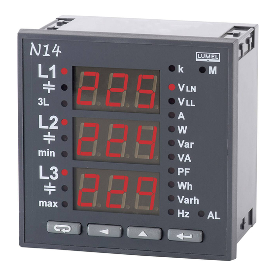
Page 4: Panel Przedni
Rys 4. Panel przedni 4.2. Komunikaty po włączeniu zasilania Po włączeniu zasilania miernik wyko- nuje test wyświetlaczy, wyświetla na- zwę miernika N14 z aktualną wersją programu oraz wykonania znamiono- we napięć i prądów. gdzie: n.nn jest numerem aktualnej wersji programu lub numerem wykonania spe- cjalnego. -
Page 5: Tryby Pracy
4.3. Tryby pracy Podane tablice znajdują się w pełnej instrukcji obsługi - dostępnej na www.lumel.com.pl Rys 6. Tryby pracy miernika N14. - Page 6 15 minut. W przypadku gdy nie upłynie pełny inter- wał czasu wyświetlany jest komunikat Err. Wyświetlanie błędów opisane zostało w punkcie 8 (patrz pełna instruk- cja obsługi - dostępna na www.lumel.com.pl). Załączenie przekaźnika alarmowego sygnalizowane jest podświetle- niem znacznika AL.
-
Page 7: Ustawienia Parametrów
4.5. Ustawienia parametrów Wejście w tryb programowania odbywa się poprzez naciśnięcie i przy- trzymanie przycisków przez około 3 sekundy. Wejście w tryb programowania chronione jest kodem dostępu. W przypadku braku kodu, pro- gram przechodzi w opcje pro- gramowania. Wyświetlany jest napis SET (w pierwszej kolum- nie) oraz symbole poszczegól- nych poziomów: P, C, A. -
Page 8: Dane Techniczne
5. DANE TECHNICZNE Zakresy pomiarowe i dopuszczalne błędy podstawowe Tablica 4 Błąd Zakres wskazań* Zakres pomiarowy Wielkość mierzona Zakres wskazań Zakres L2 L3 podsta- pomiarowy wowy Prąd 1/5 A L1...L3 0,00...9,99 kA 0,02...6 A~ ± 0,5% Napięcie L-N 0,0...289 kV 2,9...480 V~ ±... - Page 9 Stała impulsów wyjścia typu O/C: 5000 imp/kWh, niezależnie od ustawionych przekładni Ku i Ki Stopieñ ochrony zapewniany przez obudowê: - od strony czo³owej IP 40 - od czêœci zatablicowej IP 10 Masa: 0,3 kg Wymiary: 96 ´ 96 ´ 78,5 mm Warunki odniesienia i znamionowe warunki u¿ytkowania.
- Page 10 2, dla wejścia pomiarowego 600 V - kat. II (300 V - kat. III) , wysokość npm, < 2000 m. 6. KOD WYKONAŃ Kod wykonań miernika parametrów sieci N14. Tablica 5 MIERNIK PARAMETRÓW SIECI N14 - X XX X Prąd wejściowy I...
-
Page 11: Basic Requirements And Operational Safety
1. BASIC REQUIREMENTS AND OPERATIONAL SAFETY In the security scope, the meter meets the requirements of EN 61010-1 standard. Remarks concerning the operator safety: All operations concerning the meter installation and connections should be carried out by qualified skilled personnel and national regulations for the prevention of accidents must be observed. -
Page 12: Meter Description
Fig. 1. Overall meter dimensions 3. METER DESCRIPTION 3.1. Current inputs All current inputs are galvanically isolated (internal current transformers). The meter is adapted to co-operate with external measuring current transformers. Displayed current values and derived quantities are automatically re-counted by the quantity of the introduced external transformer ratio. Current inputs are defined in the order as 1 A or 5 A. -
Page 13: Frontal Panel
4.2. Messages after switching the supply on After switching the supply on, the meter carries out the display test and displays the name of the N14 meter with the current program ver- sion and rated values of voltages and currents. -
Page 14: Working Modes
4.3. Working modes * The given tables can be found in the full user manual - available at www.lumel.com.pl Fig.6. Working modes of N14 meter... - Page 15 15-min mean time. In case when the full interval of time is not expired, the message Err is displayed. The display of errors was described in the chapter 8 - see full user’s manual, available at www.lumel.com.pl. The alarm relay switching on is signaled by the AL index backlighting.
-
Page 16: Setting Of Parameters
4.5. Setting of parameters The entry in the programming mode is carried out by pressing and hol- ding during ca 3 sec. pushes. The entry in the programming mode is protected by the access code. In case when there is no code, the program transits into the programming option. -
Page 17: Power Consumption
Developed active 0 .. 99 999 999.9 kWh ± 1% energy Reactive inductive 0 .. 99 999 999.9 kVarh ± 1% energy 0 .. 99 999 999.9 kVarh Reactive capacitive ± 1% energy *depends on set ratio t_U (voltage transformer ratio: 1 .. 4000) and t_I (current transformer ratio: 1 .. -
Page 18: Electromagnetic Compatibility
- power factor: -1 .. 0 .. 1 - ambient temperature: - 25...23...+55C - storage temperature: - 30... +70C - relative air humidity: 25... 95% (condensation inadmissible) - admissible peak factor: - current: 2 - voltage: 2 - external magnetic field: 0... 40... 400 A/m - short duration overload capacity (5 s): - voltage inputs: 2 Un (max.1000 V) - current inputs: 10 In... -
Page 19: Order Codes
6. ORDER CODES Table 5 NETWORK PARAMETER METER N14 - X XX X Input current I 1 A (X/1) ..............1 5 A (X/5) ..............2 Input voltage (phase/phase-to-phase) U 3 ´ 57.7/100 V ..............1 3 ´ 230/400 V ...............2 3 ´... -
Page 20: Electrical Connections
SCHEMATY PODłĄCZEŃ ELECTRICAL CONNECTIONS Pomiar bezpośredni w sieci trójprzewodowej Direct measurement in a 3-wire network Supply OUpulse Zasilanie WYimp RS485 Zasilanie WYimp GNDI RS485 GNDI 14 13 14 13 Pomiar półpośredni w sieci trójprzewodowej Semi-indirect measurement in a 3-wire network Supply OUpulse Zasilanie... - Page 22 Supply OUpulse Pomiar bezpośredni Zasilanie WYimp RS485 w sieci czteroprzewodowej GNDI WYimp Zasilanie RS485 GNDI Direct measurement 14 13 in a 4-wire network 14 13 Zasilanie RS485 WYimp Pomiar półpośredni Supply OUpulse GNDI w sieci czteroprzewodowej WYimp Zasilanie RS485 GNDI 14 13 Semi-indirect mea- 14 13...
-
Page 24: Export Department
LUMEL S.A. ul. Sulechowska 1, 65-022 Zielona Góra, Poland tel.: +48 68 45 75 100, fax +48 68 45 75 508 www.lumel.com.pl Informacja techniczna: tel.: (68) 45 75 306, 45 75 180, 45 75 260 e-mail: sprzedaz@lumel.com.pl Realizacja zamówień: tel.: (68) 45 75 207, 45 75 209, 45 75 218, 45 75 341 fax.: (68) 32 55 650...
Need help?
Do you have a question about the N14 and is the answer not in the manual?
Questions and answers