Table of Contents
Advertisement
Advertisement
Table of Contents

Related Manuals for Lumel ND25


Summary of Contents for Lumel ND25
- Page 1 POWER NETWORK METER USER’S MANUAL FOR INTERFACE...
-
Page 3: Table Of Contents
Section Contents Introduction Communication Parameter selection screen 2.1 Address Setting 2.2 RS 485 Baud rate 2.3 RS 485 Parity 2.4 Quit Communication Parameters RS 485 ( ModBus ) Output 3.1 Accessing 3X and 4X registers for Reading Measured values 3.2 Accessing 4X register for Reading & Writing Settings 3.3 User Assignable Modbus Registers Datalogging 4.1 Event Based Datalogging... -
Page 4: Introduction
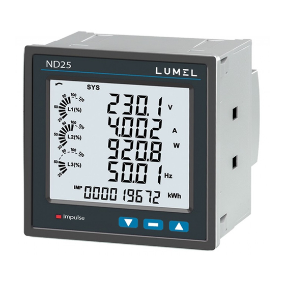
1. Introduction The Multifunction Energy Meter is a panel mounted 96 x 96mm DIN Quadratic Digital Panel Meter, which measures important electrical parameters in 3 ph 4 wire / 3 wire / 1ph Network and replaces the multiple analog panel meters. It measures electrical parameters like AC voltage, Current, Frequency, Power, Energy (Active / Reactive / Apparent), phase angle, power factor,individual harmonics &... -
Page 5: Communication Parameter Selection Screen
2. Communication Parameter Selection Screen While using USB port communication the Configuration must be : Device address: 001 Baud rate : 57600 Parity : None Stop bit: 1 2.1 Address Setting This screen applies to the RS 485 output only. This screen allows the user to set RS 485 address for the meter. -
Page 6: Rs 485 Parity
2.3 RS 485 Parity This screen allows the user to set Parity & number of stop bits of RS 485 port. Pressing “ ” key accepts the present value and advances to “Quit Communication Parameters” screen (see section 2.4). Similarly, pressing “ ”... -
Page 7: Accessing 3X And 4X Registers For Reading Measured Values
After sending any query through software (of the Master), it must allow 300ms of time to elapse before assuming that the Meter is not going to respond. If slave does not respond within 300 ms, Master can ignore the previous query and can issue fresh query to the slave. - Page 8 Note : Number of registers = Number of parameters x 2 Each Query for reading the data must be restricted to 40 parameters or less. Exceeding the 40 parameter limit will cause a ModBus exception code to be returned. Query for 3X read: 02(Hex) 00 (Hex) 01 (Hex) 04 (Hex) 00 (Hex)
- Page 9 TABLE 1 : 3 X and 4 X register addresses for measured parameters Start Address Hex 3X Start Address Hex 4X Address Address Parameter Parameter (3X) (4X) Number High Byte Low Byte High Byte Low Byte 30001 40001 30003 40003 30005 40005 30007...
- Page 10 TABLE 1 : Continued... Start Address Hex 3X Start Address Hex 4X Address Address Parameter Parameter (3X) (4X) Number High Byte Low Byte High Byte Low Byte VAr Sum 30061 40061 PF Avg 30063 40063 PF Sum 30065 40065 Phase Angle Avg 30067 40067 Phase Angle Sum...
- Page 11 TABLE 1 : Continued... Start Address Hex 3X Start Address Hex 4X Address Address Para. Parameter (3X) (4X) High Byte Low Byte High Byte Low Byte VARh Inductive 30123 40123 VAh Overflow count 30125 40125 30127 40127 System Voltage Max 30133 40133 System Voltage Min...
- Page 12 TABLE 1 : Continued... Start Address Hex 3X Start Address Hex 4X Address Address Parameter Parameter (3X) (4X) Number High Byte Low Byte High Byte Low Byte 30201 40201 30203 40203 30205 40205 VTHD-R 30207 40207 VTHD-Y 30209 40209 VTHD-B 30211 40211 ITHD-R...
- Page 13 TABLE 1 : Continued... Start Address Hex 3X Start Address Hex 4X Address Address Parameter Parameter (3X) (4X) Number High Byte Low Byte High Byte Low Byte 30293 40293 RTC Minute 30295 40295 RTC Hour 30297 40297 RTC Day 30299 40299 RTC Date 30301...
- Page 14 TABLE 1 : Continued... Start Address Hex 3X Start Address Hex 4X Address Address Parameter Parameter (3X) (4X) Number High Byte Low Byte High Byte Low Byte IR Harmonic-2 30407 40407 VR Harmonic-3 30409 40409 IR Harmonic-3 30411 40411 VR Harmonic-4 30413 40413 IR Harmonic-4...
- Page 15 TABLE 1 : Continued... Start Address Hex 3X Start Address Hex 4X Address Address Parameter Parameter (3X) (4X) Number High Byte Low Byte High Byte Low Byte IR Harmonic-17 30467 40467 VR Harmonic-18 30469 40469 IR Harmonic-18 30471 40471 VR Harmonic-19 30473 40473 IR Harmonic-19...
- Page 16 TABLE 1 : Continued... Start Address Hex 3X Start Address Hex 4X Address Address Parameter Parameter (3X) (4X) Number High Byte Low Byte High Byte Low Byte IR Harmonic-32 30527 40527 VY Harmonic-1 30529 40529 IY Harmonic-1 30531 40531 VY Harmonic-2 30533 40533 IY Harmonic-2...
- Page 17 TABLE 1 : Continued... Start Address Hex 3X Start Address Hex 4X Address Address Parameter Parameter (3X) (4X) Number High Byte Low Byte High Byte Low Byte IY Harmonic-15 30587 40587 VY Harmonic-16 30589 40589 IY Harmonic-16 30591 40591 VY Harmonic-17 30593 40593 IY Harmonic-17...
- Page 18 TABLE 1 : Continued... Start Address Hex 3X Start Address Hex 4X Address Address Parameter Parameter (3X) (4X) Number High Byte Low Byte High Byte Low Byte 30647 40647 IY Harmonic-30 30649 40649 VY Harmonic-31 30651 40651 IY Harmonic-31 30653 40653 VY Harmonic-32 30655...
- Page 19 TABLE 1 : Continued... Start Address Hex 3X Start Address Hex 4X Address Address Parameter Parameter (3X) (4X) Number High Byte Low Byte High Byte Low Byte IB Harmonic-13 30707 40707 VB Harmonic-14 30709 40709 IB Harmonic-14 30711 40711 VB Harmonic-15 30713 40713 IB Harmonic-15...
- Page 20 TABLE 1 : Continued... Start Address Hex 3X Start Address Hex 4X Address Address Parameter Parameter (3X) (4X) Number High Byte Low Byte High Byte Low Byte IB Harmonic-28 30767 40767 VB Harmonic-29 30769 40769 IB Harmonic-29 30771 40771 VB Harmonic-30 30773 40773 IB Harmonic-30...
- Page 21 TABLE 2 : 3X and 4X register addresses for 32-bit Integer Energy Start Address Hex 3X Start Address Hex Address Address Parameter (3X) (4X) Hi Byte Lo Byte Hi Byte Lo Byte Reactive Energy Imp. on time* 30831 40831 Apparent Energy on time* 30833 40833 Active Energy Imp Overflow Count on time*...
-
Page 22: Accessing 4X Register For Reading & Writing Settings
3.2 Accessing 4 X register for Reading & Writing Settings: Each setting is held in the 4X registers. ModBus code 03 is used to read the current setting & code 16 is used to write/change the setting. Refer TABLE 3 for 4X Register addresses. Example: Reading System type System type: Start address = 177A (Hex) - Page 23 Example : Writing System type System type : Start address = 177A (Hex) Number of registers = 02 Query:( Change System type to 3phase 3wire = 2 ) Device Address 01 (Hex) Byte Count : Total number of data bytes received. Data register 1 High Byte : Most significant 8 bits of Data Function Code 10 (Hex)
- Page 24 TABLE 3 : 4 X register addresses Address Read/ Default Param- Modbus Start Addr. Hex Parameter (Register) Write High Byte Low Byte Value eter No. Demand integration time R/Wp 46003 Energy Resolution / unit R/Wp 46005 System nominal Voltage 46007 System nominal Current 46009 System type...
- Page 25 TABLE 3 : continued... Address Read/ Default Param- Modbus Start Addr. Hex Parameter Write (Register) High Byte Low Byte Value eter No. Limit2 delay(On) R/Wp 46067 R/Wp Limit2 delay(Off) 46069 R/Wp Password 0000 46071 Limit1 Configuration select R/Wp 46073 Limit2 Configuration select R/Wp 46075 Auto scroll...
- Page 26 TABLE 3 : continued... Address Read/ Default Param- Modbus Start Addr. Hex Parameter (Register) Write High Byte Low Byte Value eter No. R/Wp User screen9 46155 User screen10 R/Wp 46157 Serial number 46177 Model No 46179 Version no. 46181 Restart / Reboot Meter R/Wp 46183 Event-based Datalog Select...
- Page 27 TABLE 3 : continued... Read/ Default Modbus Start Addr. Hex Address Param- Parameter Write (Register) eter No. High Byte Low Byte Value R/Wp 46233 Datalog Parameter 21 R/Wp 46235 Datalog Parameter 22 R/Wp 46237 Datalog Parameter 23 46239 Datalog Parameter 24 R/Wp 46241 Datalog Parameter 25...
- Page 28 Address Parameter Description 46013 Pulse Width This address is used to set pulse width of the Pulse output. of Relay Write one of the following values to this address: 60 : 60 ms 100 : 100 ms 200 : 200 ms This address is used to reset different parameters.
- Page 29 Address Parameter Description This address is used to set Energy Digit Reset Count value. Energy count can be Energy Digit 46039 configured to reset in between 7 to 9. Reset Count Word Order controls the order in which Multifunction Meter receives or sends 46041 Word Order floating - point numbers:- normal or reversed register order .
- Page 30 Address Parameter Description Relay 1 Off (De- This address is used to set the De-energizing delay or Off delay in seconds in Energize) Delay/ range of 1 to 9999. For RTC Relay this range is 00.00 to 23.59. 46057 Off Time 46059 Relay 2 output select...
- Page 31 Address Parameter Description 46077 Auto scroll This address is used to activate or de-activate the auto scrolling. Write 0: Deactivate 1: Activate This address is used to activate or de-activate the 30 mA noise current 30mA Noise 46079 elimination write current 0: Deactivate 30 (Decimal): Activate...
- Page 32 Address Parameter Description 46127 RTC Complete This address is used to read and write full date in “ddmmyy” format from RTC. Date 46129 RTC Complete This address is used to read and write complete time in “hh.mm” format from RTC. Time 46131 RTC Day of...
- Page 33 Address Parameter Description 46189 Time Based This address is used to read and write the interval between consecutive time log Datalog Interval entries in minutes. Valid value range 1-60 Selection 46191 Logging This value decides the number of parameters to be logged in time based Parameter Count datalogging.
- Page 34 TABLE 4 : RS 485 Set-up Code TABLE 5 : Pulse Configuration select Decimal Baud Rate Parity Stop Bit Configuration Code value Active Energy Import 4800 NONE Active Energy Export 4800 NONE Capacitive Reactive Energy 4800 EVEN Inductive Reactive Energy 4800 Apparent Energy 9600...
- Page 35 TABLE 8 : Parameters for Limit output Trip Point Parameter 100% Parameter Set Range Value ü ü ü None ü ü ü 10 - 120 % Volts 1 Vnom (L-N) ű ü ü 10 - 120 % Volts 2 Vnom (L-N) ű...
- Page 36 TABLE 8: Continued... Trip Point 100% Parameter Parameter Set Range Value ü ü ü 10 - 9999999 Wh Export ü ü ü 10 - 9999999 VAr Capacitive ü ü ü VAr Inductive 10 - 9999999 ü ü ü 10 - 9999999 ü...
- Page 37 TABLE 9: Relay Configuration For Timer or RTC relay For Limit Relay Code Configuration Code Configuration Energize when triggered Hi - alarm & energised Relay De-energize when triggered Hi - alarm & De-energised Relay Lo - alarm & Energised Relay Lo - alarm &...
- Page 38 TABLE 11 : Measurement & Energy/Counter Screens for Advanced version of ND25 Screen On Modbus On Display Parameters 3P 4W 3P 3W 1P 2W 3P 4W 3P 3W 1P 2W System Voltage/ Current/ Power/ Frequency ü ü ü ü ü...
- Page 39 TABLE 11 : Continued... On Modbus Screen On Display Parameters 3P 4W 3P 3W 1P 2W 3P 4W 3P 3W 1P 2W Individual harmonics V ü ü ü ü ü ü Individual harmonics A ü ü ü ü ü ü ü...
- Page 40 TABLE 12 : Measurement & Energy/Counter Screens for Basic version of ND25 Screen On Modbus On Display Parameters 3P 4W 3P 3W 1P 2W 3P 4W 3P 3W 1P 2W ü ü ü ü ü ü System Voltage/ Current/ Power/ Frequency ű...
- Page 41 TABLE 12 : Continued... Screen On Modbus On Display Parameters 3P 4W 3P 3W 1P 2W 3P 4W 3P 3W 1P 2W ű ű ű ű ű ű Individual harmonics V ű ű ű ű ű ű Individual harmonics A ü...
- Page 42 TABLE 13 : Datalogging Parameters List Higher Model Lower Model Para. Parameter Parameter 3P 4W 3P 3W 1P 2W 3P 4W 3P 3W 1P 2W ü ü ü ü ü ü ű ű ü ü ü ü ű ű ü ü...
- Page 43 TABLE 13 : Continued... Advanced version of ND25 Basic version of ND25 Para. Parameter Parameter 3P 4W 3P 3W 1P 2W 3P 4W 3P 3W 1P 2W ű ű ü ü ü ü VAR Avg ű ű ü ü ü...
-
Page 44: User Assignable Modbus Registers
TABLE 13: Continued... Advanced version of ND25 Basic version of ND25 Para. Parameter Parameter 3P 4W 3P 3W 1P 2W 3P 4W 3P 3W 1P 2W ű ű ű ű ü ü ü ű ű ü ű ű ű ű... - Page 45 TABLE 14 : User Assignable 3X Data Registers Address Address Modbus Start Address (Hex) Assignable Register (3X) (4X) High Byte Low Byte 31025 41025 Assignable Reg 1 Assignable Reg 2 31027 41027 Assignable Reg 3 31029 41029 Assignable Reg 4 31031 41031 Assignable Reg 5...
- Page 46 TABLE 15 : Continued... Address Modbus Start Address (Hex) Assignable Register (4X) High Byte Low Byte 49510 Mapped Add for register #0x0412 49511 Mapped Add for register #0x0414 49512 Mapped Add for register #0x0416 49513 Mapped Add for register #0x0418 49514 Mapped Add for register #0x041A 49515...
- Page 47 Reading Parameter data through User Assignable Registers: In assigning query Voltage 2 & Power Factor 1 parameters were assigned to 0x251C & 0x251D (TABLE 15) which will point to user assignable 3x registers 0x400 and 0x402 (TABLE 14). So to read Voltage2 and Power Factor1 data reading query should be as below.
- Page 48 User Assignable mapping Registers User Assignable Data Registers ( 4X Registers TABLE 14 ) ( 3X Registers TABLE 13 ) (Starting Address) (Starting Address) 0x401 0x400 0x251C 0x400 Voltage 2 (0x0004) (16 bit) (16 bit) 0x403 0x402 0x251D 0x402 Power Factor 1 (0x0020) (16 bit) (16 bit) 0x404...
-
Page 49: Datalogging
4. Datalogging Datalogging is a feature that allows the meter to store measured parameters based on time or on occurrence of a certain event. The user can retrieve the data later for further application. This meter offers three types of datalogging 1) Event based 2) Time based 3) Load profile... - Page 50 Table 16: Continued... 312349 Date 1 312409 Date 1 312351 Time 1 312411 Time 1 312353 Value 1 312413 Value 1 312355 Date 2 312415 Date 2 312357 Time 2 312417 Time 2 312359 Value 2 312419 Value 2 312361 Date 3 312421 Date 3...
- Page 51 Table 16: Continued... 312469 Date 1 312529 Date 1 312471 Time 1 312531 Time 1 312473 Value 1 312533 Value 1 312475 Date 2 312535 Date 2 312477 Time 2 312537 Time 2 312479 Value 2 312539 Value 2 312481 Date 3 312541 Date 3...
-
Page 52: Time Based Datalogging
4.2 Time Based Datalogging This type of datalogging stores data with a timestamp at a preset time interval. This can be used to take a snapshot of the system at regular time intervals. This data can be used to do in-depth analysis of the system. The number of parameters to be logged and which parameters to store can also be configured by the user through display as well as modbus. - Page 53 Query Format for Downloading the Time based datalog The query format for downloading an entry of a time datalog is given below. Maximum number of register the user can access in 1 query are limited by 64 and corresponding to it maximum byte count is 128. The byte count should be logging parameter count multiplied by 4 and added to 8, where 8 is the byte count for date and time (4 bytes x 2 parameters).
- Page 54 Response: Description The response to time datalog query contains data in Hex Value Decimal Value following structure. Dev Addr First two bytes are device address and function code, Func Code followed by number of bytes data of 1 byte and then date and a time data of 4 bytes each.
-
Page 55: Load Profile Datalogging
4.3 Load Profile Datalogging This type of datalogging stores data on each day at time 00:00. The parameters stored in this log include all energies and maximum demands. This log stores data daily as well as monthly interval. Hence, daily and monthly energy consumption can be logged. - Page 56 Query Format for Downloading the Load Profile Datalog The query format for downloading an entry of a daily load profile log is given below. Maximum number of register the user can access in 1 query are limited by 40. Query example: Example: If a user wants to access daily energy load profile Description Decimal Value...
- Page 57 Response: Description Decimal The response to the load profile query contains device address, function code and number of bytes data each Dev Addr of 1 byte, and then the requested parameters of 4 bytes Func Code each. Each parameter represents data over a period of a Number of bytes day when daily log is accessed and represents data over a period of a month when monthly log is accessed.
- Page 58 LUMEL S.A. ul. Sulechowska 1, 65-022 Zielona Góra, Poland tel.: +48 68 45 75 100, fax +48 68 45 75 508 www.lumel.com.pl Export department: tel.: (+48 68) 45 75 139, 45 75 233, 45 75 321, 45 75 386 fax.: (+48 68) 32 54 091 e-mail: export@lumel.com.pl...
Need help?
Do you have a question about the ND25 and is the answer not in the manual?
Questions and answers