Table of Contents
Advertisement
Quick Links
Advertisement
Table of Contents

Related Manuals for Lumel NR30 series


Summary of Contents for Lumel NR30 series
- Page 1 RAIL MOUNTED POWER NETWORK METER NR30 USER’S MANUAL...
-
Page 2: Table Of Contents
Contents APPLICATION ........................3 METER SET ........................3 BASIC REQUIREMENTS, OPERATIONAL SAFETY ............3 INSTALLATION ........................4 DESCRIPTION ........................4 Current inputs ....................... 4 Voltage inputs ....................... 4 Connection of the meter ....................5 External connections diagram ..................6 COOPERATION WITH S4AO .................... 9 NR30 PROGRAMMING .................... - Page 3 NR30-09A User's manual 11.3.4 Modbus TCP/IP ....................39 12 MAP OF REGISTERS OF NR30 METER ................ 39 13 FIRMWARE UPGRADE ....................56 13.1 Update of the meter website ................... 56 13.2 Firmware upgrade - the main program of the meter ..........57 14 ERROR CODES .......................
-
Page 4: Application
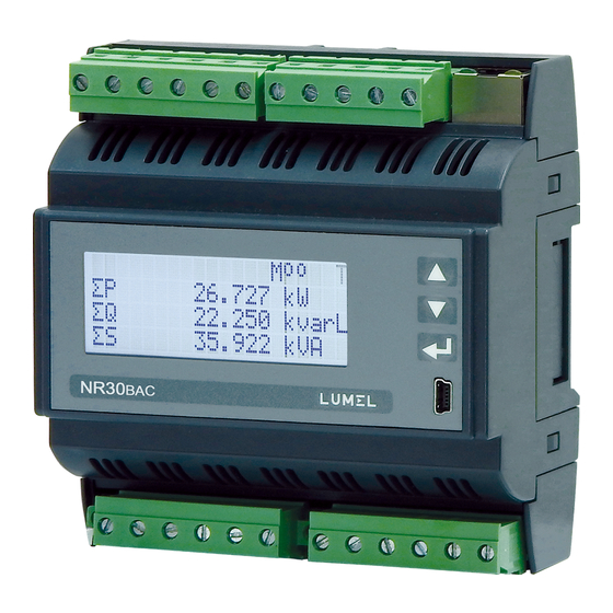
NR30-09A User's manual APPLICATION NR30 meter is a digital programmable instrument designed to measure network parameters of single-phase 2-wire and three-phase 3 and 4-wire balanced and unbalanced systems. The measured values are displayed on a 20 x 4 LCD character display. The meter enables controlling and optimizing the operation of power electronics devices, systems and industrial installations. -
Page 5: Installation
NR30-09A User's manual INSTALLATION The meter is adapted for installation in a modular installation switchgears on a 35 mm support rail. The housing of the meter is made of plastic. Housing dimensions are 105 x 110 x 60 mm. Outside the meter there are screw terminal strips that allow connection of external wires with a cross-section up to 5.3 mm / indirect measurements/ and up to 16 ²... -
Page 6: Connection Of The Meter
NR30-09A User's manual Connection of the meter Description of the meter external terminals is shown in Fig 2. Fig.2. Connection of the meter: a) in the version for indirect connections (1 / 5 A) b) in the version for direct connections ( 63 A ) -
Page 7: External Connections Diagram
NR30-09A User's manual External connections diagram Fig.3. Direct, semi-direct and indirect measurement in 1-phase network Fig.4. Direct measurement in 4-wire network version 63 A Direct measurement in 4-wire network... - Page 8 NR30-09A User's manual Semi-indirect measurement in 4-wire network Indirect measurement in 4-wire network Fig.5. Input signal connection in 3-phase 4 - wire network...
- Page 9 NR30-09A User's manual Direct measurement in 3 - wire network Semi-direct measurement using 2 current transformers in 3 - wire network. Indirect measurement using 2 current transformers and 2 or 3 voltage transformers in 3 - wire network.
-
Page 10: Cooperation With S4Ao
NR30-09A User's manual Fig.6. Input signal connection in 3-phase 3 - wire network COOPERATION WITH S4AO For NR30 versions with the S4AO block of 4 analog outputs, side connector for connecting blocks is included. The connector can also be ordered separately: order code 24-171-01-00016 connector Fig.7. -
Page 11: Nr30 Programming
NR30-09A User's manual therefore cooperation with S4AO excludes the use the NR30 meter RS485 interface for communication with another Master. NR30 PROGRAMMING Frontal panel Fig.9. Frontal panel NR30 meter has 3 buttons and a 20 x 4 LCD character display. Description of the frontal panel: value increase key and moving up... -
Page 12: 6.2. Messages After Switching The Supply On
NR30-09A User's manual pressing of the buttons (next page) or (previous page). Page size is determined by any 3 quantities selected from Table 1 and displayed on the screen. Defining pages is described under Displaying mode. The information bar at the top of the screen shows the status of the alarm outputs, alarm conditions, file archive memory status, archiving status. -
Page 13: Operating Modes
NR30-09A User's manual Fig.11. Welcome screen NR30 – meter type, brand Bv:01.06 – bootloader version no., Fv:0.80 – firmvare version no. U: 3x230.0...3x400.0 V – voltage versions 63 A – current versions OPERATING MODES The NR30 meter has 9 operating modes: Measurement –... - Page 14 NR30-09A User's manual Fig.12a. Programming matrix Fig.12b. Programming matrix...
- Page 15 NR30-09A User's manual Fig.12c. Programming matrix Fig.12d. Programming matrix...
-
Page 16: Measurement Mode
NR30-09A User's manual Fig.12e. Programming matrix Measurement mode In the Measurement mode, the values of quantities are displayed acc. to the pre-programmed or user- configured pages in the Displaying mode. The change of the page is done by pressing (next page) or button (previous page). -
Page 17: Measurement Of Voltage And Current Harmonics
NR30-09A User's manual Measurement of voltage and current harmonics 8.1.1 The choice of harmonics is made by selecting page 23 dedicated to displaying harmonic values of voltages U1, U2, U3 and currents I1, I2, I3 simultaneously for 3-phases. The number of the displayed harmonic can be changed in the range 2..51 after pressing the button and then Fig.14 Screen 23 - visualization of harmonics... -
Page 18: Alarm Mode
"Voltage L - L", the parameter "Voltage L - N" is automatically converted ( √3 ), For the configuration of NR30 meters you can also use our free eCon software available at www.lumel.com.pl Alarm mode Select the Alarms mode in options and approve the choice by pressing... - Page 19 NR30-09A User's manual Fig.16. Alarm mode screens Table 2 Parameter name range Notes / description Default value Logical conditions C1 v C2 v C3 C1 C2 C3 (C1 C2) vC3 (C1 vC2) C3 RLY state if AL on on/off State of relay with activated alarm Deactivated/Activated Holdback alarm off...
- Page 20 NR30-09A User's manual Hi limit condition -144.0…144.0 Upper value of condition 101.0 in % of the nominal value of input quantity acc. to table 7 0 … 3600 Delay of condition act. Delay condition on in seconds 0 … 3600 Delay of condition deactivation Delay condition off in seconds...
-
Page 21: Display Mode
NR30-09A User's manual "Upper value of the condition” at all phases. 3_oF – when the value of the measured quantity will be below the "Lower value of condition" or above the "Upper value of condition” at any phase - the condition is met. The condition will be disabled if the value of the measured quantity is between the "Lower value of condition"... - Page 22 NR30-09A User's manual Display field 3 a chosen page and field in depending on Page 22 accordance with table 4. connections layout En S *Page 23 is dedicated to displaying the harmonics values of voltages U1, U2, U3 and currents I1, I2, I3 and it is not possible to change the quantity in the selected field.
- Page 23 NR30-09A User's manual three-phase reactive power Q (G,M,k)var S (G,M,k)VA three-phase apparent power PF avg active power factor 3-phase (PF=P/S) tg avg tg factor 3-phase average (tg=Q/P) THD U ...
-
Page 24: Archiving Mode
NR30-09A User's manual Default settings of the displayed pages in 3-phase 3-wire system Table 5b U12 V I1 A U123 V P W PF avg P DMD W P W Q var THD U12 % THD I1 % U23 V I2 A I avg A Q var tg avg S DMD W En P+ kWh... - Page 25 NR30-09A User's manual Fig.19. Archiving mode screens Table 6 Parameter name range Notes / description Default value Archive type n_on, noFF, on,oFF, Archiving type - archiving activation n_on H_on, HoFF, 3non, 3noF, condition acc. to Fig.20 3_on, 3_oF Parameters U1, I1, P1, ... Archived quantities acc.
- Page 26 NR30-09A User's manual Archiving Archiving enabled enabled disabled disabled Tigger value Tigger value Archiving Archiving enabled enabled enabled disabled disabled disabled Tigger value Tigger value Fig.20. Types of archiving: a) n_on b) noFF c) on d) oFF Other archiving types: ...
- Page 27 NR30-09A User's manual power factor PF of L2 phase tg coefficient of phase L2 THD of L2 phase voltage** 100.00 [%] THD U2 THD of L2 phase current 100.00 [%] THD I2 voltage of L3 phase Un [V] * current in phase wire L3 In [A] * active power of L3 phase Un x In x cos(0°) [W] *...
-
Page 28: Ethernet Mode
NR30-09A User's manual Ethernet mode Select the Ethernet mode in options and approve the choice by the push-button. Fig.21. Ethernet mode screen Table 8 Parameter name range Notes / description Default value DHCP Off/on Enabling/Disabling DHCP Client (service of automatic acquiring of the meter Ethernet IP protocol parameters from External DHCP Servers within the same Local Area... -
Page 29: Modbus Mode
NR30-09A User's manual Modbus mode Select the Modbus mode in options and approve the choice by the push-button. Fig.22. Modbus mode screen Table 9 Parameter name Characteristic / Description Default value value Address 1…247 Address on the Modbus network. Baudrate 4800 b/s, 9600 b/s, Baud rate 9600 b/s... - Page 30 NR30-09A User's manual Fig.24. Information mode screen Table 11 Parameter name Characteristic / Description Default value value Type Type of meter NR30 Order code First 5 digits of ordering code e.g.12200 Boot version Loader version e.g.1.04 Program Version Version of the main meter program e.g.0.60 Serial Number ddmmxxxx...
-
Page 31: Extended Functionality
NR30-09A User's manual EXTENDED FUNCTIONALITY In the NR30 meter (for additional payment) you can activate additional functionality. This is done by entering, from the meter menu level (Information → Service code), the correct code received from the manufacturer. A detailed description of the additional functions and their activation can be found in the appropriate manuals on the manufacturer's website. -
Page 32: Downloading The Archive
NR30-09A User's manual Fig.26. Sample archive file with data Subsequent fields included in the row describing the record have the following meaning: date – the date of the data registration, the date separator character is "-" time – hour, minute, second of recorded data, the time separator is ":" ... -
Page 33: Examples Of Registers Reading And Saving
NR30-09A User's manual - 03, 04 registers reading, - 06 one register record - 16 n - registers record, - 17 device identification Default settings: address 1, baud rate 9.6 kbit/s, RTU 8N2 mode, Examples of registers reading and saving 11.2 Readout of n-registers (code 03h) Example 1 . - Page 34 NR30-09A User's manual Response: Device Number of Value from Value from Value from Value from Checksum address Function bytes the register the register the register the register 1770h(6000) 1770h(6000) 1772h(6002) 1772h(6002) E4 6F Example 4. Readout of 2 32-bit registers of float type, starting with the register addressed 1D4Ch (7500) - register values 10, 100.
-
Page 35: Ethernet 10/100-Base-T
NR30-09A User's manual Saving to n-registers (code 10h) Example 6. Readout of 2 registers, starting with the register addressed 0FA3h (4003) Recording values 20, 2000. Request: Device Address Address No. of No. of Number Value for reg. 0FA3 Value for reg. 0FA4 Checksum CRC address Function... -
Page 36: Connection Of 10/100 Base-T Interface
NR30-09A User's manual parameters of the meter can also be changed via the serial interface. Then the approval of changes is required by entering value “1” to the register 4149. After the changes are applied, the Ethernet interface is re-initialized according to the new parameters - all Ethernet interface services will be restarted. Connection of 10/100 BASE-T interface 11.3.1 To access the Ethernet services, it is required to connect the meter to the network via the RJ45 slot... -
Page 37: Web Server
NR30-09A User's manual Web server 11.3.2 NR30 meter provides its own Web server that allows remote monitoring of measured values and readout of the meter status. With the web page the user can: • obtain device information (serial number, execution code, firmware version, bootloader version, variant (standard or special), •... -
Page 38: Ftp Server
NR30-09A User's manual 11.3.2.2 Selection of Web server user The meter has two user accounts for the WWW server secured by individual passwords: • user: ”admin”, password: ”admin” - access to configuration and the preview of parameters • user: ”user”, password: ”pass” - access to the preview of parameters only. Calling the meter IP address in the browser, for example http://192.168.1.30 will show the start window in the browser where the user must enter the name and password. - Page 39 NR30-09A User's manual 11.3.3.1 Selection of FTP user The meter has two user accounts for the FTP server secured by individual passwords: • user: ”admin”, password: “admin” - access to files saving and reading • user: ”user”, password: ”passftp” - access to archive files reading only. FTP user names cannot be changed, however it is possible to change the password for each user - it is recommended to change passwords for security reasons.
-
Page 40: Modbus Tcp/Ip
NR30-09A User's manual Modbus TCP/IP 11.3.4 NR30 meter allows access to internal registers via Ethernet and Modbus TCP/IP. In order to set up a connection it is necessary to set a unique IP address for the meter and to set the connection parameters listed in Table 13. - Page 41 NR30-09A User's manual Table 15 Register Ope- Defaul Range Description address rations 4000 0…9999 Protection – password Connections layout 0 - 3Ph/4W 4001 0 .. 1 1 - 3Ph/3W 2 - 1Ph/2W Voltage at terminal 2: 0 - voltage of the first phase L1 4002 0 ..
- Page 42 NR30-09A User's manual 4000 4020 Reserved 4021 Reserved 4022 Reserved 4023 Reserved Resetting energy meters: 0 – no changes, 1- reset active energies, 4024 0…4 2 – erase reactive energies, 3 – erase apparent energies, 4 – erase all energies Resetting averaged parameters 4025 P Demand, S Demand, I Demand...
- Page 43 NR30-09A User's manual Alarm output 1 - upper value of switching condition 3 of input -1440..0..1440 4055 1100 nominal range 4056 0..3600 s Alarm output 1 – delay of condition 3 activation 4057 0..3600 s Alarm output 1 – delay of condition 3 deactivation 4058 0..3600 s Alarm output 1 –...
- Page 44 NR30-09A User's manual 4091 Reserved 4092 Reserved 4093 Reserved 4094 Reserved 4095 Reserved 4096 Reserved 4097 Reserved 4098 Reserved 4099 Reserved 4100 1..247 Address on the Modbus network. Transmission mode: 0->8n2, 1->8e1, 2->8o1, 4101 0..3 3->8n1 Baud rate: 0->4800, 1->9600 4102 0..5 2->19200, 3->38400, 4->57600, 5->115200...
- Page 45 NR30-09A User's manual 1- DHCP service enabled, after powering up, or after selecting the menu option APPL, or after entering value “1” to register 4099 the meter will automatically receive the IP address, subnet mask and gateway address from the DHCP server, the gateway address will be the address of the server which assigned the parameters to the meter, 49320...
- Page 46 NR30-09A User's manual Table 16 Register Ope- Range Description Default address rations 4200 7500 .. 7957 Register 1 of programmable read-only register group 7500 4201 7500 .. 7957 Register 2 of programmable read-only register group 7501 4202 7500 .. 7957 Register 3 of programmable read-only register group 7502 4203...
- Page 47 NR30-09A User's manual Register Ope- Range Description Default address rations 4258 7500 .. 7957 Register 59 of programmable read-only register group 7566 4259 7500 .. 7957 Register 60 of programmable read-only register group 7567 Restore factory group 0 – no changes, 1 – restore the factory 4260 group Table 18...
- Page 48 NR30-09A User's manual 7294/7094 7447 Content of register set in register 4247 7296/7096 7448 Content of register set in register 4248 7298/7098 7449 Content of register set in register 4249 7300/7100 7450 Content of register set in register 4250 7302/7102 7451 Content of register set in register 4251 7304/7104...
- Page 49 NR30-09A User's manual Register Ope- Range Description Default address rations 4337 00..50 Page 11 display 3, P1 4338 00..50 Page 12 display 1, Q1 4339 00..50 Page 12 display 2, S1 4340 00..50 Page 12 display 3, PF1 4341 00..50 Page 13 display 1, U2 4342 00..50...
- Page 50 NR30-09A User's manual Table 20 Register Ope- Range Description Default address rations 4400 Reserved 4401 0..65535 Identifier 4402 0..65535 Bootloader version x 100 4403 0..65535 Program version x100 4404 Reserved 4405 0..65535 Ordering code 4406 0..65535 Nominal voltage x10 577/2300 4407 0..65535 Nominal voltage x10...
- Page 51 NR30-09A User's manual Percentage progress in copying the internal archive to the file 4446 0..1000 archive for group 1 and 2 in Energy is made available in hundreds of watt-hours (var-hours) in double 16-bit register, and for this reason, they must be divided by 100 when calculating values of particular energy from registers, i.e.: Imported active energy = (register 4426 value x 65536 + register 4427 value) /100 [kWh] Exported active energy = (register 4428 value x 65536 + register 4429 value) /100 [kWh] Reactive inductive energy = (register 4430 value x 65536 + register 4431 value) /100 [kVarh]...
- Page 52 NR30-09A User's manual Status register 4 (address 4418, R) type of reactive power : Bit 15 – synchronizing measurement with phase L3 Bit 7 – “1” – capacitive L3 minimum Bit 14 – synchronizing measurement with phase L2 Bit 6 – “1” – capacitive L3 Bit 13 –...
- Page 53 NR30-09A User's manual Table 21 Address of Register 16-bit Operation registers address Description Unit 2x16 1032/ 32 bits 2x16 3210 6000/8000 7500 Voltage of L1 phase 6002/8002 7501 Current of L1 phase 6004/8004 7502 Active power of L1 phase ...
- Page 54 NR30-09A User's manual reached) 3 –phase active exported energy (counter up to 6096/8096 7548 99999.99 kWh) 3-phase reactive inductive energy (number of 6098/8098 7549 register 7550 overflows, reset after 9999.9 MVArh MVArh is reached) Reactive inductive energy 3 –phase (counter up to ...
- Page 55 NR30-09A User's manual 6192/8192 7596 Apparent power L3 min 6194/8194 7597 Apparent power L3 max 6196/8196 7598 Power factor (PF) L1 min 6198/8198 7599 Power factor (PF) L1 max 6200/8200 7600 Power factor (PF) L2 min ...
- Page 56 NR30-09A User's manual 6296/8296 7648 THD U2 min 6298/8298 7649 THD U2 max 6300/8300 7650 THD U3 min 6302/8302 7651 THD U3 max 6304/8304 7652 THD U min 6306/8306 7653 THD U max ...
-
Page 57: Firmware Upgrade
NR30-09A User's manual FIRMWARE UPGRADE Update of the meter website 13.1 The website can be updated via the FTP server. We update the website of the meter in the Website update tab. Copy the file NR30_upd.tar to the main folder of the meter. Then turn the meter off and on, i.e. reset the meter. The NR30_upd.tar file will be unpacked to the correct folders. -
Page 58: Firmware Upgrade - The Main Program Of The Meter
NR30 meters have a feature that allows the user to upgrade the software using a PC with eCon software. Free eCon software and update files are available at www.lumel.com.pl. Upgrade of the meter software (firmware) can be done via the RS485 interface. The update is done in LUMEL UPDATER tab. NR30 Fig.32. -
Page 59: Technical Data
NR30-09A User's manual P.CFG – displayed when the operating parameters of the meter are incorrect. The factory settings must be restored (from the menu "Settings -> Set all defaults" or via RS485). P.PAGE – displayed when the parameters related to the configuration of displayed parameters in the meter are incorrect. - Page 60 NR30-09A User's manual Power consumption: 6 VA - in power supply circuit - in voltage circuit 0.5 VA - in current circuit 0.1 VA (1/5 A); 2.0 VA (63 A) LCD display 20 x 4 rows; white background, black characters Readout field 2 programmable relays, volt free NO contacts, resistive load 0.5 Relay outputs (A1, A2)
- Page 61 NR30-09A User's manual - power supply 85..253 V a.c. (40..50..400) Hz or 90..300 V d.c. or 20..40 V a.c. or 20..60 V d.c. - input signal: 0 .. 0.1..1.2I for versions 1/5A; 0 .. 0,...1.1I for versions 63A; 0.1..0.2..1.2U for current, voltage, PF frequency 45 ..50 ..
-
Page 62: Ordering Codes
NR30-09A User's manual ORDERING CODES Ordering code of NR30 meter of power network parameters. Table 23 Meter of Power Network Parameters X X X X XX X X NR30- Input current In 1/5 A (X/1; X/5) 63 A Input voltage (phase/phase-to-phase) Un 3x57.7/100 V to 3x100/170 V 3x230/400 V to 3x400/690 V Interfaces... - Page 63 LUMEL S.A. ul. Sulechowska 1, 65-022 Zielona Góra, Poland tel.: +48 68 45 75 100, fax +48 68 45 75 508 www.lumel.com.pl Export department: tel.: (+48 68) 45 75 139, 45 75 233, 45 75 321, 45 75 386 fax.: (+48 68) 32 54 091 e-mail: export@lumel.com.pl...
Need help?
Do you have a question about the NR30 series and is the answer not in the manual?
Questions and answers