Table of Contents
Advertisement
OPERATION MANUAL / SPARE PARTS LIST
PNEUMATIC
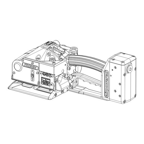
PLASTIC STRAPPING TOOL
MODEL P359
49.0524.01
CE Declaration of conformity
We declare that the machine P359
is in conformity with the following standard or
standardised documents:
2006/42/EC
Technical file at:
M.Rauch
FROMM System GmbH
Neulandstrasse 10
D-77855 Achern
25.04.2013
R.Fromm
Director
FROMM Holding AG
Hinterbergstrasse 26
CH - 6330 Cham
Advertisement
Table of Contents

Related Manuals for Fromm 49.0503


Summary of Contents for Fromm 49.0503
- Page 1 CE Declaration of conformity We declare that the machine P359 is in conformity with the following standard or standardised documents: 2006/42/EC Technical file at: M.Rauch FROMM System GmbH Neulandstrasse 10 D-77855 Achern 25.04.2013 R.Fromm Director FROMM Holding AG Hinterbergstrasse 26...
-
Page 2: Table Of Contents
INDEX PAGE SAFETY INSTRUCTIONS TECHNICAL DATA CHART OF TYPES APPROPRIATE USE INSTALLATION Compressed air connection........5 Suspension of tool . -
Page 3: Safety Instructions
SAFETY INSTRUCTIONS Read these instructions carefully. Failure to follow these instructions can result in severe personal injury. Eye injury hazard Strap breakage hazard Failure to wear safety glasses with side shields can result in Improper operation of the tool, excessive tensioning, using strap severe eye injury or blindness. -
Page 4: Technical Data
TECHNICAL DATA Description of the tool The tool model P359 has been designed to strap packages with plastic strapping. The plastic strapping is fed around the package manually or in combination with a strap feeder. The straps are inserted in the tool, tensioned, sealed by friction welding and separated from the strap coil. -
Page 5: Chart Of Types
Strap width Strap thickness Max. tension Tensioning speed lbs. mm/s inch/s 49.0503 P359/19/0.80-1.53/3.5 19.0 mm / 3/4" 0.80 - 1.53 mm / .031" - .060" 3500 49.0504 P359/19/0.80-1.53/7.0 19.0 mm / 3/4" 0.80 - 1.53 mm / .031" - .060" 7000 1570 49.0511... -
Page 6: Suspension Of Tool
Air pressure Joining thread: G 1/4, minimum Ø inside 7.2mm (0.283") Air pressure: The maximum air pressure allowed is 6.0 bar / 87 psi. The minimum working air pressure is 5.5 bar / 80 psi. Air flow of air unit*: Min.200 Nl/min / 7.06 cu.ft /min with a maximum pressure drop of 0.5 bar/ 7.25 psi. -
Page 7: Accessories
Accessories Use only parts and accessories mentioned in the operating instruction. Using other parts or accessories can cause injuries to you and other persons. Universal suspension Comfortable, stepless pivoting without moving of the suspension eye. The universal suspension can be ordered under item number P35.0230. P35.4307 Wearing plate (steel) As an option, the tool can be equipped with a... -
Page 8: Adjustments
Adjustments 5.4.1 Preselecting of strap tension and tensioning speed Do not adjust the tensioning force too high. If the tensioning force is higher than the tensioning strength of the strap, the strap will tear while the tensioning. Tensioning force and tensioning speed can be preselected at the control head. •... -
Page 9: Choose Operation Mode
5.4.4 Choose operation mode There are 2 operation modes possible. 1. Manual In this operation mode is the tensioning as well as the welding of the strap started by the operator. 2. Semi-Automatic In this operation mode the welding of the strap is automatically started as soon as the preselected tension has been reached. -
Page 10: Operation
OPERATION Feeding the strap around the package • The strapping is fed around the package as illustrated. Warning! The plastic strap which will be welded must be free from oil, grease and other dirt. Dirty plastic straps can't be welded correct! Inserting the strap •... -
Page 11: Sealing The Straps, Operation Mode Manual
Sealing the straps, Operation mode Manual • Press and release immediately the sealing button The plastic strap is welded and cut off from the strap coil at the same time. The signalisation pin is extended. After termination of the welding operation, the welding gripper and the signalisation pin remains in its position during the cooling down time. -
Page 12: Seal - Control
Seal - Control A regular control of the seal is necessary. The seal can be examined visually. Make a seal, peel it apart and examine it as follows: Correct seal The seal must be completely welded over the whole width of the strap on a length of approx. -
Page 13: Exchange Of Wearing Parts
EXCHANGE OF WEARING PARTS Before any maintenance work always disconnect the tool from the air supply. Exchange of tensioning wheel and grippers • Unscrew cover P35.4211 and remove it; • Unscrew end cover P35.0226, squeeze off from the body by means of a screwdriver; •... -
Page 14: Exchange Of Cutter, Welding Stop Gripper And Welding Gripper
Exchange of cutter, welding stop gripper and welding gripper • Remove cover P35.4213; • Remove cover P35.4212 and cover P35.4211; • Unscrew end cover P35.0226, squeeze off from the body by means of a screwdriver; • Raise tension wheel by lifting the handle lever P35.4147; •... -
Page 15: Adjustment Of The Coupler P35.0227
Assembly advise • When inserting the piston pay attention to the proper seat of the piston in the thrust piece. • Pay attention to the fitting position of the cutter (see drawing). • Safe the screws N11.1115 with Loctite 222. •... -
Page 16: Cleaning
12 WARRANTY CONDITIONS AND LIABILITY FROMM Holding AG warrants all its strapping tools and machine heads during a period of 24 months from the date of installation at the end-user's sight by the distributor, however, not later than 30 months from the date of shipment to the distributor of FROMM Holding AG. - Page 17 49052401.z...
- Page 18 N2.4902 N11.1147 N43.9195 P35.0207 N1.6503 7 P35.4165 8 N6.3223 N1.6503 P35.4123 1 P35.4167 N21.5212 P35.0206 N6.6291 P35.4114 N2.2142 N6.6117 N1.6503 P35.3143 1 P35.4166 7 P35.4165 N6.6291 N6.6117 1 N6.6220 P35.4115 P35.3143 N6.6291 N6.6117 1 P35.4113 N6.6117 N6.6217 1 N6.6117 P35.4121 1 N6.6291 P35.4116 1 P35.3143...
- Page 19 49052401.z...
- Page 20 49052401.z...
- Page 21 1 Mobilux EP2 P35.0209 2 Molykote BR 2 plus 3 Mobil Velocite No.6 1 P35.4138 4 Klüber Isoflex Alltime SL2 1 N6.6123 P35.0208 5 Klüber Isoflex NBU 15 1 N6.6255 6 Loctite 603 1 P35.4140 7 Loctite 222 1 P35.4132 8 Loctite 542 1 N6.6123 1 N6.6117...
-
Page 22: Spare Parts List 49.0524.01
13 SPARE PARTS LIST 49.0524.01 49.0524.01 P359/32/0.80-1.35/7.0 P359.0001.01 13.03.13 Item-No. in group Pcs. Description Dimension Field N1.1553 P35.0227 1 HEXAGON SCREW M4 X 8 N1.1813 P35.0212 4 RAISED CTRS. HEAD SCREW M5 X 16 N1.1919 2 SCREW M4 X 16 N1.1930 P35.0224 1 FLAT HEAD SCREW... - Page 23 1 ADHESIVE LABEL p max. 6 bar/87 psi N41.9140 1 ADHESIVE LABEL 30 X 10 X 0.1 N43.9195 1 TYPE PLATE <<P359>> N44.9104 2 ADHESIVE LABEL <<FROMM>> N6.3223 P35.0207 1 PRESSURE READING N6.5136 P35.0212 1 SEALING SCREW N6.6117 P35.0204 3 SEAL 6 X 13 X 2.3...
- Page 24 49.0524.01 P359/32/0.80-1.35/7.0 P359.0001.01 13.03.13 Item-No. in group Pcs. Description Dimension Field N6.6123 P35.0208 2 SEAL 12 X 19 X 2.3 N6.6123 P35.0209 5 SEAL 12 X 19 X 2.3 A24+ N6.6157 P35.0211 1 PACKING RING 4 MM E24+ N6.6163 P35.0221 1 SEAL 10 X 13.6 X 2.3 N6.6192...
- Page 25 49.0524.01 P359/32/0.80-1.35/7.0 P359.0001.01 13.03.13 Item-No. in group Pcs. Description Dimension Field [P35.0211] P35.0212 2 THROTTLE E23+ [P35.0212] 1 HANDLE [P35.0213] P35.0219 1 GEAR WHEEL [P35.0214] P35.0219 1 WHEEL [P35.0215] P35.0219 1 RATCHET WHEEL [P35.0216] P35.0219 1 GEAR WHEEL [P35.0219] 1 GEAR [P35.0221] 1 VALVE [P35.0222]...
- Page 26 49.0524.01 P359/32/0.80-1.35/7.0 P359.0001.01 13.03.13 Item-No. in group Pcs. Description Dimension Field P35.4126 1 BEARING SUPPORT [P35.4127] P35.0212 1 HANDLE [P35.4128] P35.0212 1 VALVE HOUSING [P35.4129] P35.0212 1 COVER P35.4130 P35.0212 1 SEAL PLATE P35.4131 P35.0208 1 VALVE STEM P35.4132 P35.0208 1 INTERMEDIATE RING P35.4133 P35.0208...
- Page 27 49.0524.01 P359/32/0.80-1.35/7.0 P359.0001.01 13.03.13 Item-No. in group Pcs. Description Dimension Field [P35.4183] 1 COVER [P35.4184] 1 HOLDER [P35.4185] 1 GRIPPER [P35.4186] 1 GRIPPER [P35.4187] 1 GRIPPER [P35.4191] 1 STRAP STOP [P35.4192] 1 STRAP STOP P35.4195 2 SPACER WASHER P35.4196 3 PINION [P35.4197] P35.0226 1 END COVER...
Need help?
Do you have a question about the 49.0503 and is the answer not in the manual?
Questions and answers