
Related Manuals for Fromm A335


Summary of Contents for Fromm A335
-
Page 1: Table Of Contents
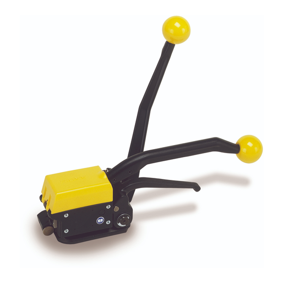
OPERATION MANUAL / SPARE PARTS LIST MANUAL SEALLESS STEEL STRAPPING TOOL MODEL A335 13.2780.01 INDEX PAGE SAFETY INSTRUCTIONS WARRANTY CONDITIONS AND LIABILITY APPROPRIATE USE TECNICAL DATA CHART OF TYPES A335 OPERATION SPARE PARTS LIST 13.2780.01 SEAL CONTROL SEAL ADJUSTMENT CLEANING ACCESSORIES... -
Page 2: Safety Instructions
SAFETY INSTRUCTIONS Read these instructions carefully. Failure to follow these instructions can result in severe personal injury. Eye injury hazard Failure to wear safety glasses with side shields can result in Strap breakage hazard severe eye injury or blindness. Always wear safety glasses with Improper operation of the tool, excessive tensioning, using strap side shields which conform to ANSI Standard Z87.1. -
Page 3: Warranty Conditions And Liability
WARRANTY CONDITIONS AND LIABILITY FROMM Holding AG warrants all its strapping tools and machine heads during a period of 90 days from the date of sale. The warranty includes all deficiencies clearly resulting from poor manufacturing or faulty materials. Damage claims as a result of production shutdowns and claims for damage to persons and to property resulting from warranty deficiencies cannot be asserted by the customer. -
Page 4: Chart Of Types A335
CHART OF TYPES A335 Item No. Model Strap width Strap thickness 13.2770 A335/12.7/0.50 - 0.58 12.7 mm / 1/2" 0.50 - 0.58 mm / 0.020 - 0.023" 13.2780 A335/13/0.50 - 0.58 13.0 mm 0.50 - 0.58 mm / 0.020 - 0.023"... - Page 5 Tensioning the strapping The tool is held tightly with the left hand being placed on the sealing lever. The tensioning handle is now moved forward and backward with the right hand until the desired tension is attained. Sealing the strapping The sealing lever is moved forward using the left hand until it hits the stop.
- Page 6 N4.1116 A33.3151 N2.2603 N1.1210 Œ A33.3110 N1.1182 Œ N2.5154 N2.3205 Œ N2.5606 Ž N1.5907 N2.1108 N2.4902 A33.3130 Œ N3.2315 Œ N2.5154 Œ A33.3144 A33.3137 A33.3131 N1.1165 Œ A33.3124 A33.1176 A33.1179 N2.2148 N3.3131 N1.3120 N2.2230 N1.3203 A33.1161 N2.5807 A33.1158 N1.6103 N1.1168 ’...
- Page 7 A33.1174 N41.9128 N4.1116 A33.1155 N41.9132 N2.2441 N2.4902 ‘ N1.1184 N1.5131 A33.3129 N1.3116 N2.4906 A33.1181 N1.1202 N2.5170 A33.1177 N2.2150 N2.1117 A33.1163 N1.6135 A33.3138 N3.2316 N3.3131 A33.3143 N2.2165 A33.3134 A33.1190 A33.1186 N2.5171 A33.1167 A33.1170 N1.1808 N1.1110 A33.1120 N1.1181 N3.3131 N1.1806 ...
-
Page 8: Spare Parts List 13.2780.01
SPARE PARTS LIST 13.2780.01 13.2780.01 A335/13/0.50-0.58 A335.0008.01 29.11.99 Item-No. in group Pcs. Description Dimension Field A33.1120 1 SHEAR BLADE A33.1137 1 DIE HALF A33.1138 1 DIE HALF A33.1155 1 SEALING HANDLE A33.1158 1 STOP A33.1161 1 BUSH A33.1163 1 SOCKET SET SCREW A33.1167... - Page 9 13.2780.01 A335/13/0.50-0.58 A335.0008.01 29.11.99 Item-No. in group Pcs. Description Dimension Field N1.3203 1 SOCKET SET SCREW M4 X 8 N1.5131 1 HEXAGON NUT N1.5907 1 HEXACON NUT N1.6103 2 WASHER 5.3 X 9.5 X 1 N1.6135 1 WASHER 15.2 X 24 X 1 N2.1108...
-
Page 10: Seal Control
SEAL CONTROL A regular control of the seal is necessary. The seal can be checked visually and the person controlling can easily judge the quality of the seal. When checking the seal the following illustrations must be compared. Correct seal A correct seal must be conform to the illustration. -
Page 11: Seal Adjustment
SEAL ADJUSTMENT The sealing and cutting depth of the sealing mechanism and the cutter can be adjusted with the use of the hexagon key N4.1408 which is supplied with the tool as follows: • Place tool as shown above. • Loosen both screws N1.1168 and open them by approx. -
Page 12: Accessories
11 ACCESSORIES Using tool with horizontal handle Upon request the tool can be supplied with a bolt A33.4101 and a grip ball N4.1116. When using tool for horizontal applications, the operator holds the tool on the grip ball during tensioning. Install the handle as follows: Remove side cover A33.1160 and break the marked position.
Need help?
Do you have a question about the A335 and is the answer not in the manual?
Questions and answers