
Related Manuals for Fromm A337.0001


Summary of Contents for Fromm A337.0001
- Page 1 OPERATION MANUAL / SPARE PARTS LIST MANUAL SEALLESS STEEL STRAPPING TOOL MODEL A337.0001 13.1880.01...
-
Page 2: Table Of Contents
INDEX PAGE SAFETY INSTRUCTIONS WARRANTY CONDITIONS AND LIABILITY APPROPRIATE USE TECNICAL DATA CHART OF TYPES A337.0001 OPERATION LEVERS OPERATION SPARE PARTS LIST 13.1880.01 SEAL CONTROL SEAL ADJUSTMENT CLEANING EXCHANGE OF WEARING PARTS SAFETY INSTRUCTIONS Read these instructions carefully. Failure to follow these instructions can result in severe personal injury. - Page 3 Joints You are fully responsible to review the joints made by your tool. Become familiar with the seal control and seal adjustment described in this operation manual. Misformed joints may not secure the load and could cause serious injury. Never handle or ship any load with improperly formed joints. Dispensing strap Only dispense strap from a dispenser specifically designed for strap.
-
Page 4: Warranty Conditions And Liability
WARRANTY CONDITIONS AND LIABILITY FROMM Holding AG warrants all its strapping tools and machine heads during a period of 90 days from the date of sale. The warranty includes all deficiencies clearly resulting from poor manufacturing or faulty materials. Damage claims as a result of production shutdowns and claims for damage to persons and to property resulting from warranty deficiencies cannot be asserted by the customer. -
Page 5: Chart Of Types A337.0001
CHART OF TYPES A337.0001 Item No. Model Strap width Strap thickness 13.1850 A337/9.5/0.38-0.50 9.5mm / 3/8" 0.38-0.50mm / .015-.020" 13.1860 A337/10/0.38-0.50 10.0mm 0.38-0.50mm / .015-.020" 13.1870 A337/12.7/0.38-0.50 12.7mm / 1/2" 0.38-0.50mm / .015-.020" 13.1872 A337/12.7/0.50-0.63 12.7mm / 1/2" 0.50-0.63mm / .020-.025"... -
Page 6: Operation Levers
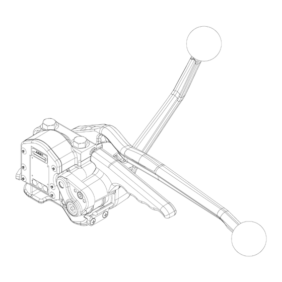
OPERATION LEVERS Tensioning handle Sealing lever Rocker OPERATION Feeding the strapping around the package The strapping is fed around the package in the direction as shown in the illustration. The strapping end is held tightly with the left hand and pulled firmly towards the operator with the right hand. - Page 7 Tensioning the strapping The tool is held tightly with the left hand being placed on the sealing lever. The tensioning handle is now moved forward and backward with the right hand until the desired tension is attained. Sealing the strapping The sealing lever is moved forward using the left hand until it hits the stop.
- Page 8 N1.1571 N1.1807 A33.7027 A33.7023 A33.0114 A33.7001 A33.7018 A33.5121 ΠA33.5122 A33.5117 ΠN3.3160 ΠA33.7017 N2.2138 A33.0105 A33.0115 N1.3513 A33.7003 ΠN3.3160 N2.2109 ΠN3.3160 A33.5118 A33.5106 ΠA33.7019 A33.7021 N2.2110 A33.7005 A33.7015 N4.9152 N2.4902 A33.5111 ΠA33.7020 N2.2147 A33.5112 N1.6203 N41.9128...
- Page 9 A33.7022 N2.4906 N1.2135 N1.1571 A33.0120 A33.7033 Œ N3.3164 N4.1116 N3.2904 Œ N2.5215 N2.2109 A33.0116 A33.0118 N1.1166 Œ A38.3129 N4.1116 N1.6207 A33.7011 Œ N1.6326 A33.7101 Œ A33.3110 Œ N1.1807 N2.5154 N11.1126 A33.7104 A33.7108 N2.1122 A33.7111 Œ A33.7113 A33.3124 Œ...
-
Page 10: Spare Parts List 13.1880.01
SPARE PARTS LIST 13.1880.01 13.1880.01 A337/13/0.38-0.50 A337.0001.01 29.02.00 Item-No. in group Pcs. Description Dimension Field [A33.0105] 1 BEARING PICK-UP ATTACHMENT [A33.0114] 1 SEALING HOUSING [A33.0115] 1 DIE AND CUTTER SUPPORT [A33.0116] 1 ROCKER [A33.0117] 1 END COVER [A33.0118] 1 TENSION HANDLE [A33.0120]... - Page 11 13.1880.01 A337/13/0.38-0.50 A337.0001.01 29.02.00 Item-No. in group Pcs. Description Dimension Field N1.3513 1 SOCKET SET SCREW M10 X 40 N1.6203 2 SPRING LOCK WASHER N1.6207 A33.0116 1 SPRING LOCK WASHER N1.6220 1 SPRING LOCK WASHER N1.6326 2 SUPPORTING DISK 30 X 42 X 2.5 N1.6503...
-
Page 12: Seal Control
SEAL CONTROL A regular control of the seal is necessary. The seal can be checked visually and the person controlling can easily judge the quality of the seal. When checking the seal the following illustrations must be compared. Correct seal A correct seal must be conform to the illustration. -
Page 13: Seal Adjustment
10 SEAL ADJUSTMENT The sealing- and cutting depth of the sealing mechanism and the cutter can be adjusted by using a hexagon key N4.1411 (size 5 mm) and turning the adjustment screw infinitely variable. The hexagon key N4.1411 is supplied with the tool. Sealing depth is excessive Turning the adjustment screw in a clockwise direction reduces the sealing depth. -
Page 14: Exchange Of Wearing Parts
12 EXCHANGE OF WEARING PARTS Exchange of the feed wheel and the gripper • Disassemble cylinder screw in the end plate. • Lift the rocker and remove end plate, strap guide, supporting disk and feed wheel from the tension shaft. •... - Page 15 Exchange of the punch, the dies and the cutter • Disassemble the ejector and the ejector screw. • Unscrew the strap stop and pull the upper ejector together with the strap stop out of the tool. • Unscrew the side plate and disassemble both guide gibs. •...
- Page 16 A3370001enT2.man...
Need help?
Do you have a question about the A337.0001 and is the answer not in the manual?
Questions and answers