Table of Contents
Advertisement
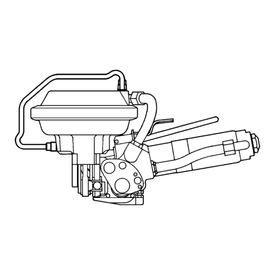
OPERATION MANUAL / SPARE PARTS LIST
PNEUMATIC COMBINATION
PUSHER TYPE TOOL
MODEL A480
13.4110.01
CE Declaration of conformity
We declare that the machine A480
is in conformity with the following standard or
standardised documents:
98/37/EEC
FROMM Holding AG
Hinterbergstrasse 26
CH - 6330 Cham
08.12 2003
R.Fromm
Director
Advertisement
Table of Contents

Subscribe to Our Youtube Channel
Related Manuals for Fromm A480


Summary of Contents for Fromm A480
- Page 1 OPERATION MANUAL / SPARE PARTS LIST PNEUMATIC COMBINATION PUSHER TYPE TOOL MODEL A480 13.4110.01 CE Declaration of conformity We declare that the machine A480 is in conformity with the following standard or standardised documents: 98/37/EEC FROMM Holding AG Hinterbergstrasse 26 CH - 6330 Cham 08.12 2003...
-
Page 2: Table Of Contents
INDEX PAGE SAFETY INSTRUCTIONS WARRANTY CONDITIONS AND LIABILITY APPROPRIATE USE CHART OF TYPES TECHNICAL DATA Dimensions without suspension bracket ......5 Steel strap . -
Page 3: Safety Instructions
SAFETY INSTRUCTIONS Read these instructions carefully. Failure to follow these instructions can result in severe personal injury. Eye injury hazard Strap breakage hazard Failure to wear safety glasses with side shields can result in Improper operation of the tool, excessive tensioning, using strap severe eye injury or blindness. -
Page 4: Warranty Conditions And Liability
WARRANTY CONDITIONS AND LIABILITY FROMM Holding AG warrants all its strapping tools and machine heads during a period of 24 months from the date of installation at the end-user's sight by the distributor, however, not later than 30 months from the date of shipment to the distributor of FROMM Holding AG. -
Page 5: Technical Data
0.3 8- 0.63 mm /.015 - .025" . Quality: The A480 model allows the use of all current steel straps with tensile strengths ranging from 87 000 to 160 000 psi (600 - 1100 N/mm Straps with a low breaking elongation are not suitable for the A480 tool. -
Page 6: Sound Information
Sound information The A-weighted equivalent continuous sound level at the work place of the machine operator is typical 83 dB (A). This value was determined according to DIN 45 635 T3 (11.85). Vibration information The weighted effective value of the acceleration typically amounts to less than 2,5m/s This value was determined according to DIN EN 28 662 T1 (01.93). -
Page 7: Maintenance
MAINTENANCE Depending on the working conditions and the use of the tool the following maintenance has to be made periodically: Air - unit • Checking the air-pressure daily. • Checking oil-level daily. • The water separator must be emptied before it is full (unless automatic). •... - Page 8 A48.1304 A48.1301 N41.9128 N41.9129 N1.1125 N1.5301 N2.5145 A48.1118 A48.1131 A48.1119 N4.9135 N1.6207 N1.1202 N1.6207 N2.4902 A48.1231 A48.1112 N2.5144 N1.5302 N1.5302 N1.5302 A48.1236 A48.1113 A48.1117 N1.1170 A48.1114 A48.1134 A48.1110 N1.6207 A48.1115 N2.5802 A48.1132 N1.1208 N1.2135 A48.1116 A48.1127 A48.1133 N1.5302 A48.1130 N2.2129 A48.1111 A48.1108 N1.2105...
- Page 9 N1.1125 N6.5195 A48.1238 A48.1120 N1.1143 Œ Loctite 222 Loctite 542 A48.1121 Ž Talkum ESSO Beacon 2 N6.6701 Molykote BR 2 plus ‘ Loctite 243 N1.2209 ’ Loctite 648 “ UHU plus Endfest 300 A48.1230 A48.1232 A48.1229 A48.1229 A48.1233 N6.6230 A48.1228...
-
Page 10: Spare Parts List 13.4110.01
SPARE PARTS LIST 13.4110.01 13.4110.01 A480/19/0.38-0.63/4.5 A480.0001.01 11.06.02 Item-No. in group Pcs. Description Dimension Field [A48.0113] 1 JAW ASSEMBLY 19 MM A48.1104 A48.0113 2 CUTTING JAW A48.1108 A48.0113 2 NOTCHING KNIFE A48.1109 A48.0113 2 JAW PIN A48.1110 A48.0113 2 FRONT TOGGLE LINK A48.1111... - Page 11 13.4110.01 A480/19/0.38-0.63/4.5 A480.0001.01 11.06.02 Item-No. in group Pcs. Description Dimension Field [A48.1306] 1 HOSE CONNECTION [L2.1108] 1 AIR MOTOR L2.1201 L2.1108 1 EXHAUST RING L2.1203 L2.1212 1 PLASTIC JACKET [L2.1212] L2.1108 1 HOUSING L2.1301 L2.1108 1 END PLATE L2.1302 L2.1108 1 PARALLEL PIN L2.1303...
- Page 12 13.4110.01 A480/19/0.38-0.63/4.5 A480.0001.01 11.06.02 Item-No. in group Pcs. Description Dimension Field N2.4902 2 HAMMER HEAD BOLT 1.85 X 4.76 N2.5102 2 PRESSURE SPRING 0.6 X 8 X 14/6 N2.5131 1 PRESSURE SPRING 0.5 X 6 X 15/7.5 N2.5144 1 PRESSURE SPRING 3 X 54 X 125/6.5...
-
Page 13: Operation
10 OPERATION 10.1 Feeding the strap The strap is fed through the seal, around the package to be strapped and again through the seal. The strap end is then bent. The operator then tensions the loose loop manually making sure that the bent strap end is adjacent to the object to be strapped. -
Page 14: Sealing The Strap
10.4 Sealing the strap The sealing valve lever A48.1233 is pressed down until the seal is notched and the upper strap sheared; the tensioning process is interrupted automatically. 10.5 Releasing the tool The tool can be released from the strapping without any further action after completing the strapping cycle.
Need help?
Do you have a question about the A480 and is the answer not in the manual?
Questions and answers