
Related Manuals for Fromm A482


Summary of Contents for Fromm A482
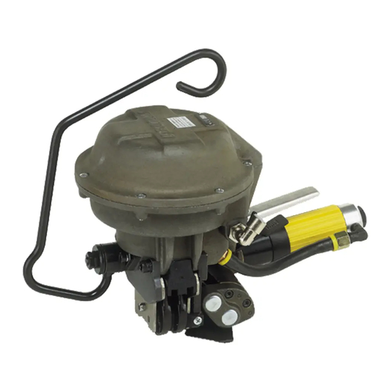
- Page 1 OPERATION MANUAL / SPARE PARTS LIST PNEUMATIC COMBINATION PUSHER TYPE TOOL MODEL A482 13.4620.01...
-
Page 2: Table Of Contents
INDEX PAGE SAFETY INSTRUCTIONS WARRANTY CONDITIONS AND LIABILITY APPROPRIATE USE TECHNICAL DATA Tool size (without suspension bracket) ....... 4 Steel strap . -
Page 3: Safety Instructions
SAFETY INSTRUCTIONS Read these instructions carefully. Failure to follow these instructions can result in severe personal injury. Eye injury hazard Strap breakage hazard Failure to wear safety glasses with side shields can result in Improper operation of the tool, excessive tensioning, using strap severe eye injury or blindness. -
Page 4: Warranty Conditions And Liability
WARRANTY CONDITIONS AND LIABILITY FROMM Holding AG warrants all its strapping tools and machine heads during a period of 90 days from the date sale. The warranty includes all deficiencies clearly resulting from poor manufacturing or faulty materials. Damage claims as a result of production shutdowns and claims for damage to persons and to property resulting from warranty deficiencies cannot be asserted by the customer. -
Page 5: Seals
Seals 19 X 0.9 X 45 mm / 3/4" X.035 X 1 3/4", push-type with overlapping flanges Joint Joint strength: approx. 75% of the tensile strength of the steel strap A double-notch (two pairs of cut notches) is made per cycle. Sound information The A-weighted equivalent continuous sound level at the work place of the machine operator is typical 83 dB (A). -
Page 6: Suspension Of Tool
Suspension of tool It is possible to suspend the tool on a spring loaded balancer using the suspension bracket A48.2303. By swivelling the bracket the tool can be suspended in its three main working positions. The suspension bracket is attached to the cover plate A48.2135 using the screws N1.1106 and the spring lock washers N1.6220 supplied with the tool. -
Page 7: Tensioning The Strapping
Tensioning the strapping The tension valve lever is pressed down. The lever is caught completely and the strap is tensioned until the air motor stalls. If the cycle has to be interrupted the catch bolt has to be pressed to the left. Sealing the strapping The sealing valve lever is pressed down until the seal is cut and the upper strap sheared;... - Page 8 A48.0103 N2.5195 N6.6235 A48.2115 A48.2133 A48.2130 A48.1237 N1.1815 N6.5133 N6.5624 N2.5216 N2.5102 N2.5161 N3.1708 N3.1706 N6.6217 N6.6204 A48.1234 A38.1202 A48.2134 A48.2136 N6.6217 A38.1208 N2.5151 N1.6206 N6.6230 N6.6204 N1.1128 A48.2132 A38.1203 A48.2125 N6.6235 A48.2128 A38.1209 N2.5159 N1.6206 N1.2212 A48.2129 A48.2135 N1.2215 A48.2110 N1.5302 A48.2106...
- Page 9 N1.1814 N1.1814 A48.2118 A48.2131 N1.2141 A48.2117 N2.5196 A48.0104 A48.2127 N2.3205 N1.1816 A48.2210 A48.2126 A48.2207 N6.6253 A48.2132 A48.2205 N3.2342 A48.2121 N3.2313 N3.4108 A48.2119 A48.2208 N1.2108 N3.4311 N1.1813 A48.2204 A48.2215 A48.2137 N3.1131 A48.1226 A48.1133 A48.1213 N1.1521 A48.1133 N1.5131 A48.2137 L2.1108 N2.2115 A48.2120 N1.1813 A48.2212 N3.2405...
-
Page 10: Spare Parts List 13.4620.01
SPARE PARTS LIST 13.4620.01 13.4620.01 A482/19/0.80/ULT/7.0 A482.0001.01 22.12.10 Item-No. in group Pcs. Description Dimension Field A38.1202 A48.0103 1 SECURITY VALVE SHELL A38.1203 A48.0103 1 VALVE BOLT A38.1208 A48.0103 1 SEALER VALVE SHELL A38.1209 A48.0103 1 VALVE BOLT A38.3405 A48.2303 2 RATCHET DISK A38.3407... - Page 11 13.4620.01 A482/19/0.80/ULT/7.0 A482.0001.01 22.12.10 Item-No. in group Pcs. Description Dimension Field A48.2213 A48.0104 1 END COVER A48.2215 A48.0104 1 WORM [A48.2217] A48.0103 1 HOSE [A48.2303] 1 SUSPENSION BRACKET [A48.2304] A48.2303 1 SUSPENSION BRACKET A48.2306 A48.2303 1 FLANGE SHAFT [L2.1103] L2.1108 1 PLANET SHAFT [L2.1108]...
- Page 12 13.4620.01 A482/19/0.80/ULT/7.0 A482.0001.01 22.12.10 Item-No. in group Pcs. Description Dimension Field N1.6206 2 SPRING LOCK WASHER N1.6207 A48.0104 2 SPRING LOCK WASHER N1.6220 A48.2303 2 SPRING LOCK WASHER N2.1202 L2.1108 1 SECURITY RING N2.2115 A48.0104 1 PARALLEL PIN 6 m6 X 20 N2.2172...
-
Page 13: Joint Control
JOINT CONTROL A regular control of the joint is necessary. The joint can be checked visually and the person controlling can easily judge the quality of the joint. Following illustration shows a proper joint: Sharp edged or misformed joints which do not appear as shown have to be taken away from the load immediately. -
Page 14: Exchange Of Wearing Parts
Model Strap width Strap thickness Strap - Max. tension Speed quality lbs. mm/s inch/s 13.4610 A482/19/0.63-0.80/ULT/4.0 19 mm / 3/4" 0.63-0.80 mm / .025"-.031" 4000 13.4620 A482/19/0.80/ULT/7.0 19 mm / 3/4" 0.80 mm / .031" 7000 1570 13.4630 A482/19/0.70-0.90/UNI/4.0 19 mm / 3/4" 0.70-0.90 mm / .027"-.035"...
Need help?
Do you have a question about the A482 and is the answer not in the manual?
Questions and answers