Sign In
Upload
Manuals
Brands
Novatel Manuals
Receiver
PwrPak7
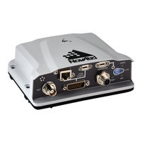
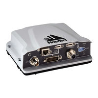
Novatel PwrPak7 Manuals
Manuals and User Guides for Novatel PwrPak7. We have
3
Novatel PwrPak7 manuals available for free PDF download: Installation And Operation Manual, Quick Start Manual
Novatel PwrPak7 Installation And Operation Manual (137 pages)
Brand:
Novatel
| Category:
Receiver
| Size: 10 MB
Table of Contents
Proprietary Notice
2
Pwrpak7 Installation and Operation User Manual
2
Return Instructions
2
Warranty
2
Table of Contents
3
Figures
7
Pwrpak7 Notices
9
Fcc
9
Innovation, Science and Economic Development (ISED) Canada
9
Ethernet Port
10
European Union (EU)
10
Pwrpak7 Wi-Fi
10
Radio Information
10
WEEE Notice
10
Wi-Fi
10
Reach
11
Rohs
11
Actions to Mitigate Lightning Hazards
12
Hazard Impact
12
Lightning Protection Installation and Grounding Procedure
12
What Is the Hazard
12
Conventions
14
Customer Support
15
Novatel Knowledge Base
15
Before Contacting Customer Support
15
Contact Information
15
Chapter 1 Pwrpak7 and Pwrpak7-E1 Overview
17
Pwrpak7 Connectors
18
Figure 1: Pwrpak7 Enclosure
18
Figure 2: Pwrpak7 Connectors
18
Table 1: Pwrpak7 Connectors
18
Pwrpak7 Leds
19
Figure 3: Pwrpak7 Status Indicators
19
Table 2: Pwrpak7 Status Indicators
20
Table 3: PWR (Power) LED
20
Table 4: GNSS LED
20
Table 5: ins LED
21
Table 6: TRANSFER LED
21
Table 7: LOG (Onboard Storage) LED
21
Related Documents and Information
22
Chapter 2 Pwrpak7 Installation
23
Shipping Box
23
Additional Equipment Required
23
Optional Accessories
23
Pwrpak7 Cables
24
Selecting a GNSS Antenna
24
Table 8: Pwrpak7 Cables
24
Choosing a Coaxial Cable
25
Power Supply Requirements for the Pwrpak7
25
Pwrpak7 Installation Overview
26
Figure 4: Pwrpak7 Installation Example
27
Mounting the GNSS Antenna
28
Antenna LNA Power
28
Mount the Pwrpak7
28
Pwrpak7 Installation and Operation User Manual
29
Mount the Pwrpak7-E1
29
Connect the Pwrpak7 to Data Communication Equipment
30
Serial Ports
30
Table 9: Pwrpak7 Serial Port Protocol
30
USB Ports
31
Wi-Fi
31
CAN Bus Port
32
Connect I/O Signals to the Pwrpak7
32
Connect Power to the Pwrpak7
32
Ethernet Port
32
Figure 5: Fuse for Pwrpak7 Power Supply
33
Fuse for the Power Supply
33
Table 10: Fuse/Holder Recommendations 12 V System
33
Figure 6: Dedicated Battery for Pwrpak7
34
Figure 7: Seamless Battery Swap
34
Seamless Battery Swap
34
Vehicle Installation
34
Check that the Pwrpak7 Is Operating
35
Chapter 3 OEM7 Receiver Operation
37
Communications with the Receiver
37
Figure 8: Basic Receiver Enclosure Connection Interfaces (Example)
37
USB Communications
38
Wi-Fi Communications
38
Serial Port Communications
39
Change the COM Port Settings
40
Configure a COM Port to Use RS-232 or
40
Ethernet Communications
40
Table 11: Serial Ports Supported
40
CAN Bus Communications
41
ICOM Communications
41
Getting Started
42
Communicating with the Receiver
42
Transmitting and Receiving Corrections
43
Figure 9: Basic Differential Setup
44
Base Station Configuration
45
Defining Antenna and Base Antenna
45
Configuration Notes
46
Rover Station Configuration
46
ALIGN Heading Master and Remote Configurations
47
Automatic Set up for Direct-Wire Connection between Master and Rover Via COM2
47
Manual Set up Via COM2
47
Glide
48
Dual-Frequency GLIDE
48
PDP and GLIDE Configurations
48
Steadyline
49
Figure 10: Positioning Change Without STEADYLINE
49
Maintain
49
Figure 11: STEADYLINE Maintain
50
Figure 12: STEADYLINE Transition
50
Figure 13: STEADYLINE Prefer Accuracy
50
Prefer Accuracy
50
Transition
50
Figure 14: STEADYLINE UAL- Warning Limit Example
51
Ual
51
Enabling Novatel CORRECT with PPP
52
Figure 15: STEADYLINE UAL - out of Bounds Example
52
Terrastar Subscriptions
53
Veripos Subscriptions
54
Enabling SBAS Positioning
52
Rtk Assist
54
Transferring Time between Receivers
55
GPS to Receiver Time Synchronization
55
Time Definitions
55
Procedures to Transfer Time
56
Figure 16: Transfer COARSE Time from Fine Clock to Cold Clock Receiver
57
Figure 17: Transfer FINE Time from Fine Clock to Cold Clock Receiver
58
Figure 18: Transfer FINE Time from Fine Clock to Warm Clock Receiver
59
Figure 19: 1 PPS Alignment
59
Interference Toolkit
60
Monitoring GNSS Signals
60
Pwrpak7 Installation and Operation User Manual
60
Monitoring Signals Using a Command Line
61
Monitoring Signals Using Novatel Connect
61
Configure Filters
63
Remove Interference Signals
63
Logging and Retrieving Data Overview
66
Pass-Through Logging
66
Saving Logs to a File
66
Logging to Internal Memory
67
Logging Using the Log Button
68
Transferring Files from Internal Memory to a USB Stick
69
Access Internal Memory with a Computer
71
Additional Features and Information
72
Strobes
72
Chapter 4 Built-In Status Tests
73
Receiver Status Word
73
RXSTATUSEVENT Log
74
RXSTATUS Log
74
Status Word
74
Error Word
74
Figure 20: Location of Receiver Status Word
74
Figure 21: Reading the Bits in the Receiver Status Word
74
Status Code Arrays
75
Figure 22: Location of Receiver Error Word
75
Figure 23: Reading the Bits in the Receiver Error Word
75
Receiver Status Code
76
Auxiliary Status Codes
76
Set and Clear Mask for All Status Code Arrays
76
Figure 24: Status Code Arrays
76
Chapter 5 Ethernet Configuration
77
Required Hardware
77
Static IP Address Configuration
77
Static IP Address Configuration-Receiver
78
Figure 25: Cross-Over Ethernet Cable Configuration-OEM7 Receiver
78
Static IP Address Configuration-Windows 7
79
Confirming Ethernet Setup
80
Dynamic IP Address Configuration
80
Figure 26: Dynamic IP Address Configuration through a DHCP Server-OEM7 Receiver
80
Base/Rover Configuration through Ethernet Connectivity
81
Figure 27: Base/Rover Ethernet Setup-OEM7 Receiver
82
Large COM Port Data Throughput
83
NTRIP Configuration
83
Figure 28: NTRIP System
84
Chapter 6 Wi-Fi Configuration
86
Enable the Wi-Fi Access Point
86
Disable Wi-Fi
86
Table 12: Wi-Fi Default Configuration
86
Change the Wi-Fi Passkey
87
Change the Wi-Fi Channel
87
Change the Wi-Fi IP Address
87
Chapter 7 CAN Bus
89
Default Configuration
90
Configuring the CAN Bus
90
Configuration Notes
90
Table 13: Default NAME
90
Example of Enabling the CAN Bus
91
Example of Modifying the CAN Bus Parameters
91
Example of Detecting an Address Claim Failure and Reconfiguring
91
Address Claim Procedure
92
NMEA2000 Logging
92
Example of NMEA2000 Log Configuration
93
Pwrpak7 Installation and Operation User Manual
93
Example of Custom PGN Configuration
93
Corrections over CAN
93
Configuring OEM7 Receivers to Use OEM6 CAN Settings
94
Example for Receiving Corrections from any Source
94
Example for Transmitting Corrections to 0X1C Node
94
Novatel Messages over CAN
94
Configuration on OEM6
95
Configuration on OEM7
95
Chapter 8 Troubleshooting
96
Table 14: Troubleshooting Based on Symptoms
96
Examining the RXSTATUS Log
97
Table 15: Resolving a Receiver Error Word
98
Table 16: Resolving an Error in the Receiver Status Word
99
Examining the AUX1 Status Word
100
Table 17: Resolving an Error in the AUX1 Status Word
100
Safe Mode
101
Recovery Steps
101
Reset Loop Detection
101
Chapter 9 Novatel Firmware and Software
103
Firmware Updates and Model Upgrades
103
Firmware Updates
103
Model Upgrades
103
Authorization Code
104
Updating or Upgrading Using the Winload Utility
105
Transferring Firmware Files
105
Using the Winload Utility
105
Figure 29: Winload's Open Window
106
Figure 30: Open File in Winload
106
Updating Using Softload Commands
107
Figure 31: COM Port Setup
107
Softload Commands and Logs
107
Working with S-Records
108
Sending Firmware Data
109
Softload Update Method
110
Softload Errors
113
Upgrading Using the AUTH Command
113
Upgrade Procedure
113
APPENDIX A Pwrpak7 Specifications
115
Table 18: Pwrpak7 Physical Description
115
Pwrpak7 Performance Specifications
116
Table 19: Pwrpak7 Receiver Performance
116
Table 20: Pwrpak7-E1 IMU Performance
117
Pwrpak7 Mechanical Specifications
119
Figure 32: Pwrpak7 Dimensions
119
Figure 33: Pwrpak7-E1 Center of Navigation
120
Pwrpak7 Electrical and Environmental Specifications
121
Table 21: Pwrpak7 Environmental Specifications
121
Table 22: Pwrpak7 Power Requirements
121
Table 23: Pwrpak7 RF Input/Lna Power Output
121
Pwrpak7 Data Communication Specifications
123
Table 24: Data Communications Interfaces
123
Pwrpak7 Strobe Specifications
125
Table 25: Pwrpak7 Strobes Description
125
Table 26: Pwrpak7 Strobe Electrical Specifications
125
Pwrpak7 Connectors
126
Table 27: Pwrpak7 Connectors
126
Table 28: 26 Pin D-SUB High Density Pin out
127
Pwrpak7 Power Cable
129
Figure 34: Pwrpak7 Power Cable
129
Table 29: Pwrpak7 Power Cable Pinout
129
Pwrpak7 All I/O Cable
130
Figure 35: Pwrpak7 All I/O Cable
130
Table 30: Pwrpak7 All I/O Cable Pinout
130
Pwrpak7 COM1 Cable
132
Figure 36: Pwrpak7 COM1 Cable
132
Table 31: Pwrpak7 COM1 Cable Pinout
132
Pwrpak7 IMU Cable
133
Figure 37: Pwrpak7 IMU Cable
133
Table 32: Pwrpak7 IMU Cable Pinout
133
APPENDIX B Importance of Antenna Selection
134
Figure 38: Plot of Good and Poor Antenna Phase Center Variation over Elevation Angle
135
Advertisement
Novatel PwrPak7 Quick Start Manual (13 pages)
Brand:
Novatel
| Category:
GPS
| Size: 0 MB
Table of Contents
Quick Start Guide
1
Optional Accessories
2
Com Ports
3
Ethernet Connection
7
Connect to a Wi-Fi Network
7
Network Security
8
Data Logging
9
Onboard Memory
9
Enabling L-Band
10
Additional Functionality
12
Questions or Comments
12
Novatel PwrPak7 Quick Start Manual (4 pages)
Brand:
Novatel
| Category:
Enclosure
| Size: 1 MB
Advertisement
Advertisement
Related Products
Novatel ProPak6
Novatel PwrPak7D
Novatel PwrPak7-E1
Novatel PwrPak7D-E1
Novatel ProPak
Novatel P720
Novatel Merlin PC720
Novatel Pinwheel OEM
Novatel AG-Star
Novatel DL-V3
Novatel Categories
Antenna
Wireless Router
Modem
Receiver
GPS
More Novatel Manuals
Login
Sign In
OR
Sign in with Facebook
Sign in with Google
Upload manual
Upload from disk
Upload from URL