
Subscribe to Our Youtube Channel
Related Manuals for Stryker Atlas 660Z


Summary of Contents for Stryker Atlas 660Z
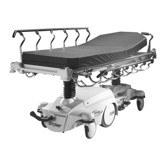
- Page 1 Atlas Transport Stretcher with Model 660Z MAINTENANCE MANUAL For Parts or Technical Assistance 1−800−327−0770 (Option 2)
- Page 2 INTRODUCTION Introduction ..............page 1−1 Specifications .
- Page 3 ASSEMBLY DRAWINGS AND PARTS LISTS Standard Base Assembly ............page 5−3 −...
- Page 4 ASSEMBLY DRAWINGS AND PARTS LISTS (CONTINUED) Standard, Removable I.V. Pole Assembly ..........page 5−54 2−Stage I.V.
- Page 5 Notes...
- Page 6 − 31.30 inHg) Ambient Temperature in Charge Mode Not to exceed 28_ C Stryker reserves the right to change specifications without notice. WARNING / CAUTION / NOTE DEFINITION The words WARNING, CAUTION and NOTE carry special meanings and should be carefully reviewed.
- Page 7 Safety Tips and Guidelines Before operating this stretcher, it is important to read and understand all information in this manual. Carefully read and strictly follow the warnings listed on this page. WARNING Patients should be discouraged from sitting directly on the ends of the stretcher. Excessive weight will cause the litter surface to tip up, possibly causing patient injury.
- Page 8 Safety Tips and Guidelines WARNING Hand wash all surfaces of the frame with warm water and mild detergent. Dry thoroughly. DO NOT STEAM CLEAN, PRESSURE WASH, HOSE OFF OR ULTRASONICALLY CLEAN. Using these methods of cleaning is not recommended and may void this product’s warranty. Inspect the mattress cover after each use. Dis- continue use if any cracks or rips are found in the cover which may allow fluids to enter the mattress.
- Page 9 Set−Up Procedures It is important that the Model 660Z Stretcher is working properly before it is put into service. The following list will help ensure that each part of the unit is checked. Plug the power cord into a properly grounded, hospital grade wall receptacle. The 12 volt batteries that provide power to the drive wheel and back−up power to the unit functions will charge whenever the power cord is plugged into the wall socket.
- Page 10 Symbols Warning, Refer to Service/Maintenance Manual Alternating Current Type B Equipment: equipment providing a particular degree of protection against elec- tric shock, particularly regarding allowable leakage current and reliability of the protec- tive earth connection. Class 1 Equipment: equipment in which protection against electric shock does not rely on BASIC INSULATION only, but which includes an additional safety precaution in that means are provided for the connection of the EQUIPMENT to the protective earth con- ductor in the fixed wiring of the installation in such a way that ACCESSIBLE METAL...
- Page 11 If requested by Stryker, products or parts for which a warranty claim is made shall be returned prepaid to Stryker’s factory. Any improper use or any alteration or repair by others in such manner as in Stryker’s judgement affects the product materially and adversely shall...
- Page 12 Stryker will perform all service during regular business hours (9−5) * Replacement parts and labor for products under PM contract will be discounted. ** Does not include any disposable items, I.V. poles (except for Stryker HD permanent poles), mattresses, or damage re- sulting from abuse.
- Page 13 Notes page 1−8 660 Zoom Stretcher 0660−009−002 REV E...
- Page 14 Preventative maintenance should be performed at a minimum of annually. A preventative maintenance pro- gram should be established for all Stryker Medical equipment. Preventative maintenance may need to be performed more frequently based on the usage level of the product.
- Page 15 If these types of products are used to clean Stryker patient handling equipment, measures must be taken to insure the stretchers are rinsed with clean water and thoroughly dried following cleaning. Failure to properly rinse and dry the stretchers will leave a cor- rosive residue on the surface of the stretcher, possibly causing premature corrosion of critical components.
-
Page 16: Table Of Contents
GENERAL INFORMATION This section contains tool lists and step−by−step procedures to assist with the maintenance and servicing of your equipment. In the text, the words “right” and “left” refer to the right and left sides of a patient lying face up on the bed. MAINTENANCE CONTENTS Litter Top Removal . -
Page 17: Litter Top Removal
Litter Top Removal Required Tools: 1/2” Socket w/Extension 3/8” Drive Ratchet Standard Screwdriver Side Cutters 1. Unplug the stretcher power cord from the wall socket. 2. Using the foot pedal, pump the litter top all the way up. 3. Lift up on the base hood at the patient, left side and unplug the communication coil cord from the electrical box. -
Page 18: Jack Removal
Jack Removal HEAD END JACK REMOVAL 1/2” Socket w/Extension 3/8” Drive Ratchet Required Tools: 1. Remove the litter from the stretcher (see page 3−2 for procedure). 2. Using a 1/2” socket with extension and a 3/8” drive ratchet, remove the two hex head screws holding the jack base to the stretcher base frame. - Page 19 Jack Removal FOOT END JACK REMOVAL 1/2” Socket w/Extension 3/8” Drive Ratchet Required Tools: 1. Remove the litter from the stretcher (see page 3−2 for procedure). 2. Using a 1/2” socket with extension and a 3/8” drive ratchet, remove the kep nut securing the plastic battery cover to the batteries.
-
Page 20: Battery Removal
Battery Removal Required Tools: 1/2” Socket w/Extension 3/8” Drive Ratchet 1. Unplug the stretcher power cord from the wall socket. 2. Using the foot pedal, pump the litter top all the way up. 3. Remove the four Phillips head cap screws holding the Zoomr carriage access panel to the plastic base hood. -
Page 21: Zoomr Carriage Assembly Removal Page 3−6
Zoomr Carriage Assembly Removal Required Tools: 1/2” Socket w/Extension 3/8” Drive Ratchet 1. Remove the litter from the stretcher (see page 3−2 for procedure). 2. Put the base brake/steer pedal in the steer position. 3. Remove the rue ring cotter and clevis pin holding the brake rod drive link to the brake rod at the head end of the stretcher base. -
Page 22: Overtravel Spring Assembly Removal Page 3−7
Overtravel Spring Assembly Removal Required Tools: 1/2” Socket w/Extension 3/8” Drive Ratchet 1. Remove the Zoomr carriage assembly (see procedure on page 3−6). 2. Remove the four hex head screws holding the overtravel spring assembly to the stretcher base frame. 3. -
Page 23: Brake Ring Removal
Brake Ring Removal Required Tools: 9/16” Socket w/Extension 3/8” Drive Ratchet Needle−Nose Pliers 1. Using needle−nose pliers, unhook the extension springs from the top of the base caster tubes. 2. Remove the plastic caster covers. 3. While putting pressure on the caster carriage bolt, use a 9/16” socket and a 3/8” drive ratchet to remove the caster nut on both sides of the stretcher. -
Page 24: Pcb Box Assembly Removal
PCB Display Box Assembly Removal Required Tools: 7/16” Socket w/Extension 3/8” Drive Ratchet T−40 & T−27 Torx Sockets 1/2” Wrench 1. If the unit is equipped with an IV Pole, remove the nut and bolt holding the IV pole in the socket and remove the IV pole. - Page 25 Notes page 3−10 660 Zoom Stretcher 0660−009−002 REV E...
- Page 26 PART NAME PART NUMBER Battery Replacement Kit ..........1040−030−000 C−Spine Cassette Holder .
- Page 27 Notes page 4−2 660 Zoom Stretcher 0660−009−002 REV E...
- Page 28 GENERAL INFORMATION This section contains assembly drawings and parts lists to assist with the identification of individual compo- nents of the equipment and accessories. In the parts lists, the words “right” and “left” refer to the right and left sides of a patient lying face up on the stretcher.
- Page 29 ASSEMBLY DRAWINGS AND PARTS LISTS CONTENTS (CONTINUED) Standard, Removable I.V. Pole Assembly ..........page 5−54 2−Stage I.V.
- Page 30 Standard Base Assembly Assembly part number 1040−010−001 (reference only) page 5−3 660 Zoom Stretcher 0660−009−002 REV E...
- Page 31 Standard Base Assembly See Detail C Ground Cable from Carriage Electronics Box DETAIL C Cam Hanger Bracket HEAD END Standard Power Cord 1040−060−060 (see page 5−29) Cord Reel Option 1040−060−050 (see page 5−29) page 5−4 660 Zoom Stretcher 0660−009−002 REV E...
- Page 32 Standard Base Assembly 1040−010−320 1040−060−050 or Cord 1040−060−060 Clamp See Detail D DETAIL B DETAIL D See Detail B HEAD END To handle control box See Detail E DETAIL E FOOT END page 5−5 660 Zoom Stretcher 0660−009−002 REV E...
- Page 33 Standard Base Assembly See Detail F DETAIL F Item Part No. Part Name Qty. Item Part No. Part Name Qty. 0005−040−000 Carriage Bolt 0081−330−000 Radial Bearing 0011−447−000 Washer (page 5−16) Base Ass’y/Std. Brakes 0013−038−000 Ext. Tooth Lock Washer (page 5−7) Brake Rod Assembly 0014−007−000 Washer (page...
- Page 34 1040−003−191 Brake Rod Assembly Item Part No. Part Name Qty. 0026−067−000 Slotted Spring Pin 1040−003−013 Brake Rod 0753−003−099 Butterfly “V” Pedal page 5−7 660 Zoom Stretcher 0660−009−002 REV E...
- Page 35 Cam Arm Assembly Assembly part number 1040−006−001 (reference only) page 5−8 660 Zoom Stretcher 0660−009−002 REV E...
- Page 36 Cam Arm Assembly Item Part No. Part Name Qty. 0003−082−000 Hex Hd. Cap Screw 0011−447−000 Washer 0014−063−000 Washer 0014−101−000 Wave Washer 0016−036−000 Nylock Hex Nut 0003−074−000 Hex Hd. Cap Screw 0023−301−000 Hex Washer Hd. Screw 0004−560−000 Soc. Hd. Cap Screw 0026−287−000 Clevis Pin 0027−020−000...
- Page 37 Overtravel Spring Assembly Assembly part number 1040−007−001 (reference only) Item Part No. Part Name Qty. Item Part No. Part Name Qty. 0011−447−000 Washer 0081−240−000 Flange Bearing 0016−036−000 Nylock Hex Nut 1040−007−003 Fork Tray 0026−330−000 Clevis Pin 1040−007−005 Lift Fork Weldment 0026−331−000 Clevis Pin 1040−007−011...
- Page 38 Zoom Carriage Assembly Assembly part number 1040−020−001 (reference only) 1040−010−821 Ground Cable page 5−11 660 Zoom Stretcher 0660−009−002 REV E...
- Page 39 Zoom Carriage Assembly Battery Cable 1040−010−810 page 5−12 660 Zoom Stretcher 0660−009−002 REV E...
- Page 40 Zoom Carriage Assembly 1040−010−836 1040−010−837 1040−010−808 TO MOTOR 1040−010−838 Bar Code 1040−010−807 page 5−13 660 Zoom Stretcher 0660−009−002 REV E...
- Page 41 Zoom Carriage Assembly Item Part No. Part Name Qty. 0005−020−000 Carriage Bolt 0011−013−000 Washer 0013−038−000 External Tooth Lock Washer 0038−151−000 Cable Tie 0014−097−000 Washer 0014−099−000 Washer 0015−012−000 Hex Jam Nut 0016−033−000 Kep Nut 0016−049−000 Nylock Hex Nut 0023−288−000 Hex Washer Hd. Screw 0023−301−000 Hex Washer Hd.
- Page 42 1040−030−000 Replacement Battery Assembly NEGATIVE TERMINAL BLACK CABLE POSITIVE TERMINAL RED CABLE Item Part No. Part Name Qty. 0005−020−000 Carriage Bolt 0016−033−000 Kep Hex Nut 0059−201−000 Battery 1040−010−871 Battery Cable 0013−038−000 Ext. Tooth Lock Washer page 5−15 660 Zoom Stretcher 0660−009−002 REV E...
- Page 43 Base Assembly with Standard Brakes Assembly part number 1040−003−005 (reference only) page 5−16 660 Zoom Stretcher 0660−009−002 REV E...
- Page 44 Base Assembly with Standard Brakes Item Part No. Part Name Qty. 0005−039−000 Step Bolt 1040−010−024 Hood Mount 0016−035−000 Nylock Hex Nut 0016−049−000 Nylock Hex Nut 0027−012−000 Hitch Pin 0028−037−000 External Retaining Ring 0038−439−000 Extension Spring 0081−272−000 Roller Bearing 0753−003−006 Brake Ring Weldment 0753−003−066 Clevis Pin 0753−003−079...
- Page 45 753−010−020 8” Caster Assembly Item Part No. Part Name Qty. 0715−002−025 Wheel 0003−099−000 Hex Hd. Cap Screw 0753−010−021 Caster Horn w/Bearing 0016−060−000 Centerlock Nut page 5−18 660 Zoom Stretcher 0660−009−002 REV E...
- Page 46 Base Assembly with Dual−Sided Hydraulics Assembly part number 1040−005−100 (reference only) Insert pump ram into keyhole slot on both ends. Lower pump connecting rod weldment onto pump ram as shown. Insert item W to retain pump 0753−002−025 Constant Descent Jacks connecting rod.
- Page 47 Base Assembly with Dual−Sided Hydraulics SEE DETAIL A Insert item ”S” into keyhole in item ”V” and push down DETAIL A Insert spring hook thru hole in pump connecting rod weldment Attach other hook to return spring hook as shown. Insert spring hook into hook on release pedal assembly.
- Page 48 Base Assembly with Dual−Sided Hydraulics SEE DETAIL C SEE DETAIL B Insert foot end release rod into release valve assembly as shown DETAIL C Insert head end release rod into release valve assembly as shown DETAIL B page 5−21 660 Zoom Stretcher 0660−009−002 REV E...
- Page 49 Base Assembly with Dual−Sided Hydraulics Item Part No. Part Name Qty. 0011−023−000 Washer 0014−071−000 Washer 0023−288−000 Hex Washer Hd. Screw 0027−031−000 Hair Pin Cotter 0038−497−000 Extension Spring (page 5−23) Release Pedal Assembly 0753−004−014 Head End Release Rod 0753−004−032 Release Pedal Swivel 0753−005−037 Pump Connecting Rod 0753−005−044...
- Page 50 753−004−001 Release Pedal Assembly Item Part No. Part Name Qty. 0715−001−333 Release Rod Stop Sleeve 1061−201−127 Short Uni Pedal 0753−004−004 Release Pedal Weldment 0753−004−121 Release Pedal Mtg. Plate 0025−171−000 Blind Rivet 0753−004−036 Bushing 0753−004−035 Rel. Pedal Bumper Strip page 5−23 660 Zoom Stretcher 0660−009−002 REV E...
- Page 51 0753−005−185 Head End Pump Pedal Assembly Item Part No. Part Name Qty. 0026−343−000 Groove Pin 0715−001−140 Vinyl Tube 0753−005−044 Pump Pedal Bushing 0753−005−180 Head End Pump Pedal Weldment 0753−201−126 Pump Pedal page 5−24 660 Zoom Stretcher 0660−009−002 REV E...
- Page 52 0753−002−025 Constant Descent Jacks Assembly Item Part No. Part Name Qty. 0023−288−000 Hex Washer Hd. Screw 0753−002−001 Constant Descent Jack Ass’y 0753−010−007 Reservoir Clamp page 5−25 660 Zoom Stretcher 0660−009−002 REV E...
- Page 53 Label 0660−001−116 See Below for Colors 0660−001−015 Specification Label Item Part No. Part Name Qty. 1040−010−017 Stryker Logo Label 1040−010−134 Zoom Bellows Assembly (page 5−28) Zoom Base Hood 1040−010−016 Zoom Logo Label Set Part Number Brake/Drive Label, Brake/Drive Label, Lift/Lower Label, Left...
- Page 54 Zoom Base Labeling Assembly BASE HOOD DEPARTMENT LABELS Department Label P/N Department Label P/N Emergency 1010−900−215 Nuclear Medicine 1010−900−255 PACU 1010−900−220 Ambulatory Surgery 1010−900−260 Transport 1010−900−225 G.I. Lab 1010−900−265 Surgery 1010−900−230 Cath. Lab 1010−900−270 Extended Stay 1010−900−235 Same Day Surgery 1010−900−275 Maternity 1010−900−240...
- Page 55 1040−010−310 Zoom Base Hood Assembly Item Part No. Part Name Qty. 0001−001−000 Flat Head Socket Screw 0014−105−000 Countersunk Washer 0052−902−000 U−Nut Fastener 1040−010−006 Base Hood 1040−010−007 Electrical Hood page 5−28 660 Zoom Stretcher 0660−009−002 REV E...
- Page 56 1040−060−060 Standard Power Cord Assembly Item Part No. Part Name Qty. 0034−406−000 Strain Relief 0039−255−000 Power Cord 1040−060−033 Cord Bracket 1040−060−050 Optional Cord Reel Assembly Female IEC Male Plug Cord to Control Box Item Part No. Part Name Qty. 0003−214−000 Hex Hd.
- Page 57 Litter Assembly Assembly part number 0660−430−010 (reference only) page 5−30 660 Zoom Stretcher 0660−009−002 REV E...
- Page 58 Litter Assembly HEAD END page 5−31 660 Zoom Stretcher 0660−009−002 REV E...
- Page 59 Litter Assembly HEAD END 1040−050−001 or 1040−150−001 (no I.V.) Communication Coil Cord (from base) page 5−32 660 Zoom Stretcher 0660−009−002 REV E...
- Page 60 Litter Assembly Item Part No. Part Name Qty. 0003−355−000 Hex Hd. Cap Screw 0003−358−000 Hex Hd. Cap Screw 0004−330−000 Soc. Hd. Cap Screw 0005−022−000 Carriage Bolt 0011−360−000 Washer 0013−010−000 Ext. Tooth Lock Washer 0014−021−000 Washer 0015−027−000 Jam Nut 0016−117−000 Hex Lock Nut 0016−118−000 Hex Lock Nut 0022−010−000...
- Page 61 29” Zoom Handle Assembly Assembly part number 1040−050−029 (reference only) Load Cell Cable Communication Cable From Electronics Box page 5−34 660 Zoom Stretcher 0660−009−002 REV E...
- Page 62 29” Zoom Handle Assembly Item Part No. Part Name Qty. 0023−288−000 Hex Washer Hd. Screw 0003−367−000 Hex Hd. Cap Screw 0013−019−000 Ext. Tooth Lock Washer 0013−038−000 Ext. Tooth Lock Washer 0023−305−000 Hex Washer Hd. Screw 0028−196−000 External Retaining Ring 1040−050−108 Pivot Bolt 1001−226−016 Pivot Bearing...
- Page 63 1040−050−030 Right Handle Grip Assembly See Detail A WIRE ROUTING DETAIL A WIRE ROUTING SIDE 2 page 5−36 660 Zoom Stretcher 0660−009−002 REV E...
- Page 64 1040−050−030 Right Handle Grip Assembly Item Part No. Part Name Qty. 0023−302−000 Pan Hd. Thrd.−Frm. Screw 1040−050−031 Light Pipe 1040−050−032 Grip Button 1040−050−303 Right Top Grip 1040−050−034 Right Bottom Grip 1040−050−035 Right Handle Weldment 0038−111−000 Cable Tie 1040−050−801 Handle Switch Cable 1040−050−802 Handle Extension Cable 0038−523−000...
- Page 65 1040−050−040 Left Handle Grip Assembly See Detail A WIRE ROUTING DETAIL A WIRE ROUTING SIDE 2 page 5−38 660 Zoom Stretcher 0660−009−002 REV E...
- Page 66 1040−050−040 Left Handle Grip Assembly Item Part No. Part Name Qty. 0023−302−000 Pan Hd. Thrd.−Frm. Screw 1040−050−031 Light Pipe 1040−050−032 Grip Button 1040−050−043 Left Top Grip 1040−050−044 Left Bottom Grip 1040−050−045 Left Handle Weldment 0038−111−000 Cable Tie 1040−050−801 Handle Switch Cable 1040−050−802 Handle Extension Cable 0038−523−000...
- Page 67 Siderail−to−Litter Assembly, Fold−to−Head page 5−40 660 Zoom Stretcher 0660−009−002 REV E...
- Page 68 Siderail−to−Litter Assembly, Fold−to−Head FOOT END page 5−41 660 Zoom Stretcher 0660−009−002 REV E...
- Page 69 Siderail−to−Litter Assembly, Fold−to−Head Item Part No. Part Name Qty. 1001−226−116 Pivot Bearing 1001−226−016 Pivot Bearing 1001−226−015 Pivot Sleeve 1001−226−107 Siderail Spring 1001−326−027 Right Spindle 1001−326−031 Lock Spindle Weldment, Rt. 1001−326−028 Left Spindle 1001−326−033 Lock Spindle Weldment, Lt. 1001−226−020 Siderail Spring Spacer 0025−172−000 Semi−Tubular Rivet 1010−226−082...
- Page 70 Siderail−to−Litter Assembly, Fold−to−Foot page 5−43 660 Zoom Stretcher 0660−009−002 REV E...
- Page 71 Siderail−to−Litter Assembly, Fold−to−Foot HEAD END page 5−44 660 Zoom Stretcher 0660−009−002 REV E...
- Page 72 Siderail−to−Litter Assembly, Fold−to−Foot Item Part No. Part Name Qty. 1001−226−116 Pivot Bearing 1001−226−016 Pivot Bearing 1001−226−015 Pivot Sleeve 1001−226−017 Siderail Spring 1001−326−027 Right Spindle 1001−326−031 Lock Spindle Weldment, Rt. 1001−326−028 Left Spindle 1001−326−033 Lock Spindle Weldment, Lt. 1001−226−020 Siderail Spring Spacer 0025−172−000 Semi−Tubular Rivet 1010−226−082...
- Page 73 1211−127−000 Optional Dual Siderail Latch Assembly FOOT END Item Part No. Part Name Qty. Item Part No. Part Name Qty. 0003−359−000 Hex Hd. Cap Screw 1001−226−045 Latch Spacer 0007−070−000 Truss Hd. Mach. Screw 1001−226−161 Dual Latch Cable Ass’y 0016−118−000 Nylock Nut 1001−226−142 Latch Pin 1001−226−147 Dual Latch Pivot 0038−222−000 Extension Spring...
- Page 74 Pneumatic Fowler Assembly Assembly part number 0660−031−010 (reference only) HEAD END Item Part No. Part Name Qty. 0003−360−000 Hex Hd. Cap Screw 0004−104−000 But. Hd. Cap Screw 0011−179−000 Washer 0014−021−000 Washer 0016−116−000 Hex Nut 0016−119−000 Hex Nut 0015−060−000 Metric Jam Nut 1211−131−026 Gas Spring Cap 0052−306−000...
- Page 75 Fowler Assembly Assembly part number 1711−131−020 (reference only) Item Part No. Part Name Qty. Item Part No. Part Name Qty. 1001−001−036 Hole Plug 0016−118−000 Hex Nut 1211−231−025 Trip Bar Pivot 0004−455−000 But. Hd. Cap Screw 1501−031−013 Fowler Tube 0037−064−000 Grommet Bumper 1510−231−012 Fowler Skin (Fiberresin) 0007−070−000 Truss Hd.
- Page 76 Fiberresin Stationary Foot Section Assembly Assembly part number 1731−019−001 (reference only) Item Part No. Part Name Qty. 0025−171−000 Blind Rivet 0037−208−000 Hole Plug 0753−010−032 Fiberresin Ft. Section Skin 7900−001−102 Velcro Pile 24 1/2” page 5−49 660 Zoom Stretcher 0660−009−002 REV E...
- Page 77 Transfer System to Litter Assembly Assembly part number 1211−132−003 (reference only) HEAD END Item Part No. Part Name Qty. 0011−418−000 Washer (page 5−51) Transfer System Ass’y, Lt. (page 5−52) Transfer System Ass’y, Rt. 0016−119−000 Nylock Nut 0003−360−000 Hex Hd. Cap Screw page 5−50 660 Zoom Stretcher 0660−009−002 REV E...
- Page 78 Transfer System Assembly, Left Assembly part number 1211−232−007 (reference only) Item Part No. Part Name Qty. (page 5−53) Transfer Board Assembly 1211−132−016 Transfer Bd. Swivel 1211−132−020 Transfer Bd. Link 1211−132−031 Transfer Bd. Pivot Ass’y, Lt. 0026−076−000 Spring Pin 0026−112−000 Spring Pin 0011−350−000 Washer 1211−232−011...
- Page 79 Transfer System Assembly, Right Assembly part number 1211−232−008 (reference only) Item Part No. Part Name Qty. (page 5−53) Transfer Board Assembly 1211−132−016 Transfer Bd. Swivel 1211−132−020 Transfer Bd. Link 0026−076−000 Roll Pin 0026−112−000 Roll Pin 0011−350−000 Washer 1211−132−030 Transfer Bd. Pivot Ass’y, Rt. 1211−232−012 Transfer Bd.
- Page 80 Transfer Board Assembly Assembly part number 1211−132−009 (reference only) Item Part No. Part Name Qty. 0025−125−000 Pop Rivet 0025−126−000 Pop Rivet 1211−132−004 Transfer Board 1211−132−017 Transfer Bd. Sleeve Wldmt. 1211−132−019 Stiffener Weldment page 5−53 660 Zoom Stretcher 0660−009−002 REV E...
- Page 81 1211−151−000 Foot End Steering Handles Assembly HEAD END Item Part No. Part Name Qty. 0003−356−000 Hex Hd. Cap Screw 0003−355−000 Hex Hd. Cap Screw 0016−118−000 Fiberlock Nut 0023−282−000 Self−Tapping Screw 0023−283−000 Self−Tapping Screw 0026−114−000 Roll Pin 1211−030−034 Cover, Hole/Slot 1211−030−037 Cover, Hole/Hole 1211−351−004 P.U.P.
- Page 82 1211−351−010 Handle Assembly Item Part No. Part Name Qty. 1010−354−024 Stop Link 1211−151−018 Sleeve Assembly 0026−118−000 Roll Pin page 5−53.2 660 Zoom Stretcher 0660−009−002 REV E...
- Page 83 0390−025−000 Standard, Removable I.V. Pole Assembly Item Part No. Part Name Qty. 0390−003−056 Knob 0390−003−053 Double I.V. Ass’y 0393−003−043 Tube Assembly 0004−496−000 Soc. Hd. Cap Screw page 5−54 660 Zoom Stretcher 0660−009−002 REV E...
- Page 84 Optional 2−Stage I.V. Assembly Assembly part numbers 1711−110−000 (Head End) 1711−112−000 (Foot End) FOOT END HEAD END Item Part No. Part Name Qty. 0003−356−000 Hex Hd. Cap Screw 0004−452−000 But. Hd. Cap Screw 0016−116−000 Fiberlock Nut 0016−118−000 Fiberlock Nut 1211−310−112 I.V.
- Page 85 1211−210−010 Optional 2−Stage I.V. Pole Assembly Item Part No. Part Name Qty. 0008−031−000 Soc. Hd. Cap Screw 0052−017−000 Washer 0926−400−162 Spacer 1211−210−029 2nd Stage Assembly 1001−359−013 Dampener 1001−159−028 Base Tube 1010−059−016 I.V. Hook (page 5−57) I.V. Pole Latch 1001−359−112 Pivot page 5−56 660 Zoom Stretcher 0660−009−002 REV E...
- Page 86 1211−210−026 I.V. Pole Latch Assembly Item Part No. Part Name Qty. 0028−167−000 Retaining Ring 0031−004−000 Steel Ball 0038−392−000 Crest−to−Crest Spring 1211−091−034 Release Label 1211−110−018 I.V. Latch Seal 1211−110−020 Washer 1211−110−021 I.V. Latch Locking Pin 1211−110−022 I.V. Latch Guide 1211−110−024 I.V. Latch O.D. Housing 1211−110−035 Washer 1211−110−036...
- Page 87 Optional 3−Stage I.V. Assembly Assembly part numbers 1711−111−000 (Head End) 1711−113−000 (Foot End) FOOT END HEAD END Item Part No. Part Name Qty. 0003−356−000 Hex Hd. Cap Screw 0004−452−000 But. Hd. Cap Screw 0016−116−000 Flexlock Nut 0016−118−000 Fiberlock Nut 1211−310−112 I.V.
- Page 88 1211−211−010 Optional 3−Stage I.V. Pole Assembly Item Part No. Part Name Qty. 0007−004−000 Truss Hd. Machine Screw 0026−076−000 Roll Pin 0052−017−000 Spacer 1211−210−031 2nd Stage Assembly 0926−400−162 Spacer (page 5−60) 3rd Stage Assembly 1001−161−023 Base Tube 1010−059−016 I.V. Hook 1010−061−014 Collar (page 5−57)
- Page 89 1211−110−032 3rd Stage Assembly − 3−Stage I.V. Pole Item Part No. Part Name Qty. 0031−021−000 Ball 0038−303−000 Compression Spring 1010−061−013 Ball Retainer 1010−061−016 Retaining Shaft 1010−061−017 Thumb Knob 1010−061−018 Hand Guard 1211−110−117 1211−110−033 3rd Extension Rod page 5−60 660 Zoom Stretcher 0660−009−002 REV E...
- Page 90 0926−039−000 Optional Defibrillator Tray Assembly Assembly part number 0926−039−000 (reference only) Umbrella Nut/Crosstube Detail Strap Securing Detail Item Part No. Part Name Qty. Item Part No. Part Name Qty. 0946−039−004 Tray 0946−039−003 Support Tube 0926−039−016 Crosstube 0926−001−082 Label 0025−055−000 Rivet 1010−050−021 Long Strap 0926−039−009 Cover 0946−001−283 Label...
- Page 91 1010−050−100 Foot Extension/Defibrillator Tray Assembly Assembly part number 1010−050−210 (reference only) Label Detail Label Detail Item Part No. Part Name Qty. Item Part No. Part Name Qty. 0008−049−000 Socket Hd. Shoulder Bolt 1010−050−050 Knob 0014−020−000 Nylon Washer 1010−050−057 “Max. Weight” Label 0014−021−000 Nylon Washer 1010−050−205 Cushion Assembly 0016−028−000 Fiberlock Nut...
- Page 92 0926−040−000 Foot Board/Chartholder Assembly Assembly part number 0926−040−010 (reference only) Item Part No. Part Name Qty. 0946−028−011 Chart Holder 0946−029−006 Foot Board 1020−030−000 Upright Oxygen Bottle Holder Assembly Item Part No. Part Name Qty. 1020−030−011 Upright Bottle Holder 0027−012−000 Cotter Pin 1020−030−017 Specification Label page 5−63...
- Page 93 1711−243−010 X−Ray Cassette to Fowler Assembly p/n 0016−118−000 Stover Locknut Item Part No. Part Name Qty. (page 5−65) X−Ray Cassette Ass’y 0025−121−000 Rivet page 5−64 660 Zoom Stretcher 0660−009−002 REV E...
- Page 94 1711−243−020 Fowler X−Ray Cassette Assembly Item Part No. Part Name Qty. 0926−023−069 Washer 0926−023−070 Block Assembly 0926−023−071 Bushing 1010−023−028 Tray Angle 1020−023−021 Knob Assembly 0001−030−000 Flat Hd. Mach. Screw 0014−003−000 Thrust Washer 1711−243−012 X−Ray Cassette Tray 1010−023−018 Warning Label 1711−243−025 Specification Label page 5−65 660 Zoom Stretcher 0660−009−002 REV E...
- Page 95 1001−055−000 Heel Stirrup and Support Assembly Assembly part number 1001−055−010 (reference only) Item Part No. Part Name Qty. 0003−359−000* Hex Hd. Cap Screw 0011−159−000 Flat Washer 0016−118−000 Nylock Hex Nut (page 5−67) Stirrup Support Ass’y, Rt. (page 5−68) Stirrup Support Ass’y, Lt. (page 5−69) Stirrup Assembly...
- Page 96 1001−055−015 Right Stirrup Support Assembly Item Part No. Part Name Qty. 0650−002−032 Lock Screw Assembly 0966−051−019 Wedge Lock, Modified 1001−055−011 Mounting Bracket 1010−055−016 Right Support Tube Wldmt. 0004−494−000 Soc. Hd. Cap Screw 0011−410−000 Washer 1211−117−016 Knob 0026−007−000 Roll Pin 0038−171−000 Compression Spring page 5−67 660 Zoom Stretcher 0660−009−002 REV E...
- Page 97 1001−055−016 Left Stirrup Support Assembly Item Part No. Part Name Qty. 0650−002−032 Lock Screw Assembly 0966−051−019 Wedge Lock, Modified 1001−055−011 Mounting Bracket 1010−055−026 Left Support Tube Wldmt. 0004−494−000 Soc. Hd. Cap Screw 0011−410−000 Washer 1211−117−016 Knob 0026−007−000 Roll Pin 0038−171−000 Compression Spring page 5−68 660 Zoom Stretcher 0660−009−002 REV E...
- Page 98 1010−055−029 Heel Stirrup Assembly Item Part No. Part Name Qty. 0390−020−013 Stirrup 0390−020−009 Stirrup Holder Assembly 1010−055−030 Extension Tube Assembly 0024−011−000 Knob 0026−043−000 Roll Pin 0022−008−000 Drive Screw page 5−69 660 Zoom Stretcher 0660−009−002 REV E...
- Page 99 1001−070−000 C−Spine Cassette Holder Assembly Item Part No. Part Name Qty. 1010−070−025 I.V. Adaptor 1010−070−018 Specification Label 0011−447−000 Flat Washer 0004−054−000 But. Hd. Cap Screw (page 5−71) Support Pole Assembly (page 5−72) Storage Bracket Ass’y 0016−118−000 Nylock Nut 0003−356−000 Hex Hd. Cap Screw 1001−070−011 Attachment Bracket 0003−355−000...
- Page 100 1010−070−010 C−Spine Support Pole Assembly View A−A Item Part No. Part Name Qty. 1010−070−033 Support Tube Cap 0026−006−000 Roll Pin 1010−070−034 Support Arm Weldment 1010−070−042 Cassette Holder Weldment 1010−070−050 Adjustment Tube Weldment 1010−070−030 Base Tube Weldment 1010−070−045 Knob 0025−055−000 Pop Rivet 1010−070−044 Pivot Pin 0026−005−000...
- Page 101 1010−070−019 C−Spine Storage Bracket Assembly 6.5” (Ref.) 2” (Ref.) Item Part No. Part Name Qty. 1010−070−020 Storage Bracket Weldment 1010−070−045 Knob 1010−070−023 Storage Label page 5−72 660 Zoom Stretcher 0660−009−002 REV E...
- Page 102 1040−010−090 Optional O2 Bottle Retainer Assembly Base Hood Item Part No. Part Name Qty. 1040−010−091 Bottle Retainer 1040−010−092 Scrulok Fastener page 5−73 660 Zoom Stretcher 0660−009−002 REV E...
- Page 103 Mattresses and Siderail Pads Mattress, 4” Thick x 31” Wide, Enhanced Comfort ....part # 0660−030−004 Mattress, 5” Thick x 31” Wide, Ultra Comfort .
- Page 104 European Representative Stryker EMEA RA/QA Director Stryker France ZAC Satolas Green Pusignan Av. De Satolas Green 69881 MEYZIEU Cedex France 3800 E. Centre Ave., Portage, MI 49002 (800) 327−0770 www.stryker.com JH 5/06 0660-009-002 REV E...
Need help?
Do you have a question about the Atlas 660Z and is the answer not in the manual?
Questions and answers