Table of Contents
Advertisement
Quick Links
INSTRUCTION
MANUAL
n
Please read manual carefully before you attempt to use your
tool so that you may use it properly and safety.
Product Operational Information
This instruction manual is written in English.
EN
Instruction manuals in other languages can be downloaded from the URL below.
Ce manuel d'instructions est rédigé en anglais.
FR
Les manuels d'instructions dans d'autres langues peuvent être téléchargés à partir de l'URL
ci-dessous.
Diese Bedienungsanleitung ist auf Englisch verfasst.
DE
Bedienungsanleitungen in anderen Sprachen können von der unten genannten URL
heruntergeladen werden.
Il presente manuale di istruzioni è redatto in lingua inglese.
IT
I manuali di istruzioni in altre lingue possono essere scaricati dal seguente URL.
Este manual de instrucciones está escrito en inglés.
ES
En la dirección URL indicada abajo se pueden descargar los manuales de instrucciones en otros
idiomas.
Este manual de instruções está escrito em inglês.
PT
Pode descarregar os manuais de instruções nos outros idiomas a partir do URL indicado abaixo.
http://www.nitto-kohki.co.jp/e/prd/delvo/index.html
[Specifications]
Lever Start
DLV30S06L-AY
Model
Push to Start
DLV30S06P-AY DLV30S12P-AY DLV30S20P-AY DLV45S06P-AY DLV45S12P-AY DLV70S06P-AY
Model
Low torque spring: 0.4 to 1.6 (3.5 to 14.2)
Torque
[Nm(Lb-in)]
High torque spring: 1.2 to 3.0 (10.6 to 26.6)
Free Speed
160 to 650
[min
]
-1
•
Please refer to p. 5 for details.
Keep the manual handy - so you can use it whenever necessary.
• Due to continuous product development/improvement the specifications and configurations in
this document are subject to change without prior notice.
Manufactured by.
NITTO KOHKI CO., LTD.
TV07521-1_DLV30S12P-AYK_en.indb
1
Professional tool
Model: DLV30S/DLV45S/DLV70S AY Series
DLV30S12L-AY
DLV30S20L-AY
300 to 1200
500 to 2000
9-4, NAKAIKEGAMI 2-CHOME, OHTA-KU, TOKYO, 146-8555, JAPAN
Tel : +81-3-3755-1111 Fax : +81-3-3753-8791
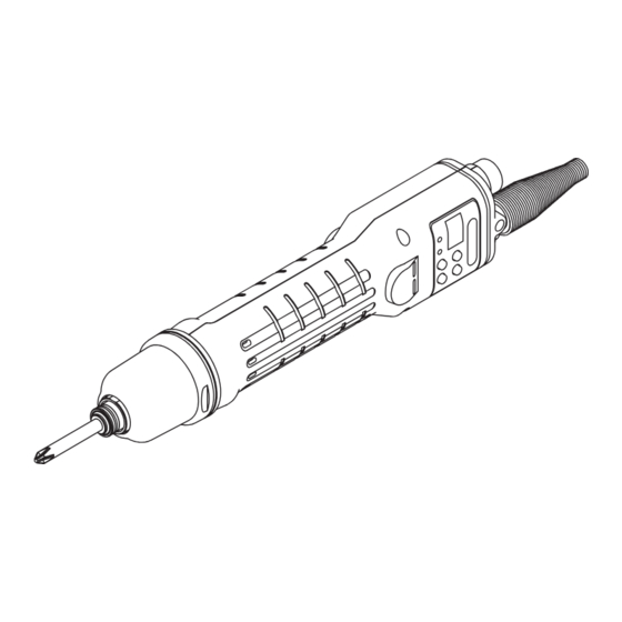
ELECTRIC SCREWDRIVER
Indoor Use Only
Brushless Motor
ESD Protection
DLV45S06L-AY
DLV45S12L-AY
2.0 to 4.5
(17.7 to 39.8)
160 to 650
300 to 1200
DLV70S06L-AY
3.8 to 7.0
(33.6 to 61.9)
160 to 650
(Original Instructions)
2017/02/10
15:56:29
Advertisement
Table of Contents

Subscribe to Our Youtube Channel
Related Manuals for Nitto Kohki DLV30S06L-AY


Summary of Contents for Nitto Kohki DLV30S06L-AY
- Page 1 • Due to continuous product development/improvement the specifications and configurations in this document are subject to change without prior notice. Manufactured by. 9-4, NAKAIKEGAMI 2-CHOME, OHTA-KU, TOKYO, 146-8555, JAPAN NITTO KOHKI CO., LTD. Tel : +81-3-3755-1111 Fax : +81-3-3753-8791 (Original Instructions) TV07521-1_DLV30S12P-AYK_en.indb...
-
Page 2: Table Of Contents
Thank you very much for your purchase of this Nitto Kohki product. Before using your tool, please read this manual carefully so that you may use it properly to get the most out of it. Please keep the manual handy - so you can use it whenever necessary. -
Page 3: Product Specific Safety Rules
Product Specific Safety Rules WARNING z Use the dedicated power supply at all times. This tool requires a dedicated power supply provided by our company. Using other power supplies could result in a fire or accident. z Do not look directly into the LED (light-emitting part) from close up. Powerful LED light could damage your eyes. -
Page 4: Application
1 Application This is a hand-held electric screwdriver used to tighten screws. The tool is equipped with an environmentally-friendly brushless motor and can be set to handle various screw tightening. You can use functions such as auto switching of the speed, display of the number of screws tightened, measuring of the screw fastening time, and interlocking with screw tightening to improve efficiency and quality of screw tightening as well as to prevent human error. -
Page 5: Part Names
Torque Scale (standard) 7 Rubber Ring (the color varies by model) d Torque Adjustment Ring Model Rubber Ring Torque adjustment ring cover Lever start type Push start type Color Material DLV30S06L-AY DLV30S06P-AY Yellow DLV30S12L-AY DLV30S12P-AY Blue Resin DLV30S20L-AY DLV30S20P-AY DLV45S06L-AY... -
Page 6: Motion Setting Unit (Led And Buttons)
Motion setting unit (LED and buttons) WARNING z Do not look at the LED (light-emitting part) from close up. In addition, do not bring it near people's eyes. Powerful LED light could damage people's eyes. CAUTION z Do not apply a shock (such as dropping) or excessive load to the motion setting unit. Doing so could cause a failure. -
Page 7: Specifications
When the output torque is measured by some other measuring device or combination, the value may be different. z The output torque and torque that occurs in screws do not match. Use a torque wrench to check the torque generated on screws. Lever Start DLV30S06L-AY DLV30S12L-AY DLV30S20L-AY Model Push to Start... - Page 8 DLV30S/45S/70S Series common specifications Duty Cycle ON 0.5 sec / OFF 3.5 sec 75 (uncertainty :K=3dB) Noise emission (dB) (According to EN60745) Vibration level (m/s Less than 2.5 (According to EN60745) protection Complied with IEC61340-5-1 Operating -5 to +50 (+23 to +122) Temperature Range (°C (°F)) Storage -20 to +70 (-4 to +158)
-
Page 9: Torque And Speed Graph
Torque and speed graph Torque scale and output torque (for reference) CAUTION z The torque scale is for reference. The output torque range is not guaranteed. Make sure to measure torque. z Use the tool within the specified range. z When the torque decreases, increase the torque based on the measured value. Series Series Torque Scale... - Page 10 Speed level and speed (for reference) CAUTION z The speed is for reference. The speed changes by the temperature of the tool, mechanical loss, and grease conditions. It could vary depending on differences in the tool itself. z When the speed is changed, the motor sound changes. This is not an error. Speed Level (Lv) Speed Level (Lv) Speed Level (Lv)
-
Page 11: Preparation
5 Preparation Attaching a bit WARNING z Before attaching or detaching a bit, always turn OFF the power. Pull the sleeve Insert a bit while pulling the sleeve Sleeve Release the sleeve and make sure the bit does not come off To remove the bit, pull out the bit while pulling the sleeve. -
Page 12: Replacing A Torque Spring
Replacing a torque spring WARNING z Before attaching or detaching the torque spring, always turn OFF the power. CAUTION z The spring plate assembly must be oriented correctly. The ball goes into the recess of the torque adjustment ring. When it is attached in the opposite orientation, the torque adjustment ring easily gets loose. -
Page 13: Attaching The Pistol Grip
Attaching the Pistol Grip WARNING z Before attaching or detaching the Pistol Grip, always turn OFF the power. z After fixing the Pistol Grip with the screw, check for looseness, slip, and displacement of the screw. CAUTION z Use care not to lose parts. Match the rib of the Pistol Grip body A and the groove of the frame handle Match the semicircle cut-out of the Pistol Grip body A and the semicircle rib of the frame handle. -
Page 14: Notes On Attaching A Commercially Available Fixing Jig
Notes on attaching a commercially available fixing jig CAUTION z Do not block the hole on the frame handle, as doing so could cause a failure due to heating. Hole Fixing position of fixing jig TV07521-1_DLV30S12P-AYK_en.indb 2017/02/10 15:56:31... -
Page 15: Basic Operation
6 Basic Operation Start WARNING z Make sure to properly connect the connection plug of the power cord and power plug. z Always make sure the tool is grounded. No grounding the tool could cause failure or electric shock at the time of electrical leakage. If you are not sure about the grounding of the outlet, request an electrical contractor to check if it is grounded. -
Page 16: Changeover Switch
Screw fastening mode Screw count The screw count is displayed on the parameter LED and the workpiece LED lights in green. When operation (rotation) is possible, this status is called “screw fastening mode.” Lights in green Changeover switch CAUTION z Do not operate the changeover switch while the tool is rotating. Doing so could cause a failure. z When the tool is not used, set the switch to neutral position. -
Page 17: Start And Stop
Start and stop WARNING z Never touch the bit while it is rotating. z Do not direct the bit toward people or animals. CAUTION z Make sure to properly press the start switch. Slide the changeover switch to the direction in which you want the tool to rotate and press the start switch to start. Releasing the start switch stops rotation. -
Page 18: Screw Tightening
Screw tightening WARNING z Firmly hold the main body to avoid losing your grip. CAUTION z Properly apply the bit end to the screw head. z Check that the bit is not worn. Slide the changeover switch to the “R” side Apply the bit end to the screw head and press the start switch When the electric driver stops, release the start switch When screw tightening is completed according to the setting... -
Page 19: Adjusting The Output Torque
Adjusting the output torque WARNING z Before adjusting the output torque, always turn OFF the power. CAUTION z The torque scale is a standard. The output torque range is not guaranteed. Turn the torque adjustment ring cover counterclockwise to remove it To increase the output torque, turn the torque adjustment ring clockwise To decrease the output torque, turn the torque adjustment ring counterclockwise White paint... -
Page 20: Basic Settings
7 Basic Settings Operation mode The tool can be set to handle various screw tightening. You can enter each mode from the screw fastening mode. For details on operation and the operation of each function, see the reference page. Mode Operation Operation to return to screw fastening mode Reference Press and hold the [MEMORY] button or... -
Page 21: Function Settings List
Function settings list CAUTION z Always record the set values. You can utilize “Setting memo” (p. 70). If the tool fails, all settings may be initialized. Also, settings may be initialized at the time of repair in order to check operation. Please note that there is no function to output the set values to an outside device. -
Page 22: Ng Display
NG display When NG operation occurs, the parameter LED displays a No. from E1 to E9 and the main LED lights in red. While the main LED lights in red, the electric screwdriver does not operate (rotate). Parameter LED Details When rotation stopped before the lower limit of screw fastening time elapses (when torque reached the set torque or the start switch is pressed) When the screwdriver is rotating longer than the upper limit of screw fastening time... -
Page 23: Initialization Of Settings
Initialization of settings It is possible to initialize settings to the factory default. Note that the security setting performed from the remote controller (sold separately) cannot be canceled. Also, the settings cannot be initialized while the security is set. Turn OFF the security setting and perform initialization. CAUTION z When initialization is performed, all settings return to the default. -
Page 24: Changing Channels
8 Changing Channels Channel setting mode The folder where the “Motion settings list” (p. 18) is saved is called a “channel” and 8 channels can be used by switching. This mode can be used when function No. 12 “Channel switching method” is set to “0: Inside screwdriver.” (p. 60) In screw fastening mode, press and hold the [UP] button The buzzer sounds, the main LED lights in red and the workpiece LED goes OFF. -
Page 25: Checking The Channel
Checking the channel While in screw fastening mode, you can check the current channel and set a value. Slide the changeover switch to the “-” (neutral) side Press the start switch Lever start type Push start type While pressing the start switch, the channel No. and set value are displayed in order on the parameter LED. Displays Channel No. -
Page 26: Motion Setting
9 Motion Setting Switching the motion setting mode Set the electric screwdriver motion (rotation) for each channel. In screw fastening mode, press and hold the [MEMORY] button and the [UP] button The buzzer sounds, the main LED lights in purple and the workpiece LED goes OFF. Lights in purple Channel No. -
Page 27: Setting The Screw Count
Setting the screw count In screw fastening mode, press and hold the [MEMORY] button and the [UP] button The buzzer sounds, the main LED lights in purple and the workpiece LED goes OFF. The mode enters motion setting mode. Use the [UP] button or [DOWN] button to set the screw count (1 to 99) Pressing and holding the button increases the count. -
Page 28: Setting The Speed Level And Time
Setting the speed level and time You can change the speed during screw tightening. By combining low speed and high speed, work efficiency and quality can be improved. CAUTION z When the speed difference is great, it may take time for the speed to be switched. Set this item after checking the actual rotation status. - Page 29 Variable setting: twice Speed When the speed is great, it may take time for the speed to be switched. 1 Middle 2 Finish Time 3 Start 4 Rotation time at start 5 Rotation time at middle 6 Lower limit of screw fastening time 7 Upper limit of screw fastening time 8 OK range Variable setting: once...
-
Page 30: Setting Auto Reverse Mode
Setting auto reverse mode Auto reverse mode means a motion to switch the electric screwdriver rotation direction automatically to the reverse. This mode is used when tightening a screw temporarily, intentionally loosening a screw (screws for terminal blocks, etc.) or checking a screw hole. CAUTION z When the setting is “Reverse after the lower limit of screw fastening time”, if the lower limit of screw fastening time is set to 0 sec. - Page 31 Timing chart When the torque reaches the set torque during reverse rotation in auto reverse mode, NG occurs and the parameter LED displays E4. When the start switch is released during reverse rotation in auto reverse mode, NG occurs and the parameter LED displays E5.
- Page 32 Stop at reverse after the lower limit of screw fastening time Speed 1 Middle 2 Finish 3 Start 4 Stop Time 5 Rotation time at start 6 Rotation time at middle 7 Lower limit of screw fastening time TV07521-1_DLV30S12P-AYK_en.indb 2017/02/10 15:56:35...
-
Page 33: Measuring The Screw Fastening Time
10 Measuring the Screw Fastening Time By setting the screw fastening time, it is possible to manage the length of screws to be used or screw fastening failure. This function measures the maximum and minimum values of the screw fastening time and by updating the value an optimum value can be found. -
Page 34: Setting Of The Screw Fastening Time And Rotation Time
Setting of the screw fastening time and rotation time Using the screw fastening time measurement mode, you can set the screw fastening time and each rotation time easily. CAUTION z Periodically measure the screw fastening time. The speed has individual differences and it changes by impacts such as heating or mechanical loss. We recommend that the screw fastening time be measured periodically. - Page 35 Motion Adjust the upper limit of screw fastening time value and lower limit Setting value, respectively Optional For example, set the upper limit of screw fastening time to +10% (ex: 0.77 sec.) and the lower limit of screw fastening time to -10% (ex. 0.54 sec.). When setting values, consider tolerances such as the screw length.
-
Page 36: Setting Functions
11 Setting Functions By setting various functions of electric driver, work quality can be improved. For the setting value of each function, see “Function settings list” (p. 19). Function settings are applied to all channels. Functions cannot be assigned for each channel. In screw fastening mode, press and hold the [MEMORY] button and [SELECT] button The buzzer sounds, the main LED lights in green and the workpiece LED goes off. -
Page 37: Adjusting The Screw Fastening Confirmation Time
Adjusting the screw fastening confirmation time During the screw fastening confirmation time, you can reverse screw tightening. Use this period for rework time or confirmation work time. The main LED lights in green during the screw fastening confirmation time, and when the OK signal (output signal issued when a series of work is completed) is output after the screw fastening confirmation time, the main LED lights in blue. -
Page 38: Adjusting The Ng Signal Output Time
Adjusting the NG signal output time You can check the NG content by setting the NG signal output time. When resuming work after NG work, if you have set the NG display to continue, you can understand that the work is interrupted by NG work. When NG operation occurs, the parameter LED displays a No. - Page 39 Timing chart When NG display is set to “0: Do not continue” 1 NG occurs 2 NG signal output time 3 Lights in red 4 NG display MAIN LED 5 Screw fastening mode 6 Operation disabled 7 Operation enabled 8 Returns to screw fastening mode automatically When NG display is set to “1: Continue”...
-
Page 40: Resetting The Screw Count
Resetting the screw count You can reset the screw count during work. In screw fastening mode, press and hold the [SELECT] button Press and hold The screw count returns to the initial set value. Reset is possible during the screw fastening confirmation time. TV07521-1_DLV30S12P-AYK_en.indb 2017/02/10 15:56:35... -
Page 41: Return The Screw Count One By One
Return the screw count one by one You can return the screw count one by one in the middle of work. This function is called the count return function. You can return the screw count one by one during the screw fastening confirmation time. In screw fastening mode, press and hold the [MEMORY] button and [SELECT] button The mode enters function setting mode. -
Page 42: Counting Method Of Screw Fastening Count
Counting method of screw fastening count You can change the counting method of the screw count. In screw fastening mode, press and hold the [MEMORY] button and [SELECT] button The mode enters function setting mode. Press the [SELECT] button to select function No. 10 Use the [UP] button or [DOWN] button to select the counting method Setting Setting details... -
Page 43: Locking Button Operations
Locking button operations To prevent careless incorrect operation, you can lock button operations (Key lock). In screw fastening mode, press and hold the [MEMORY] button Press and hold The parameter LED displays “LO” and the keys are locked. To unlock the keys, press and hold the [MEMORY] button again Press and hold The parameter LED displays “UL”... -
Page 44: Making Settings Using The Remote Controller
12 Making Settings Using the Remote Controller The remote controller (sold separately) can be used to easily change settings of the electric screwdriver from a distance. When you use the remote controller, you can change the settings of multiple electric screwdrivers while checking on the LCD Also, some functions can only be set from the remote controller. -
Page 45: Receiving Data From The Remote Controller
Receiving data from the remote controller When data is received from the remote controller, the main LED lights in blue. When reception is successful, the main LED flashes in blue and the mode returns to screw fastening mode. Lights in blue Flashes in blue Receiving Received successfully... -
Page 46: Using External Signals
13 Using External Signals You can input or output external signals via an external signal connector. A signal cable inserted into the external signal connector is sold separately. (p. 65) CAUTION z There is no internal power supply. Supply power (24 VDC) from outside. z Before connecting the wire for the external signal, always turn OFF the power. -
Page 47: External Signal Specifications
Pull the sleeve Attach the signal cable When removing the cable, pull the sleeve and then pull out the signal cable. Insert External signal specifications I/O circuit CAUTION z There is no internal power supply. Supply power (24 VDC) from outside. Input circuit Electric screwdriver internal circuit Input signal... -
Page 48: Connection Example Of I/O Signal
I/O signal specifications Photocoupler input Input signal 24 VDC 5 mA per input PNP open collector Output signal 24 VDC Max. 30 mA per output Connection example of I/O signal WARNING z Before connecting the wire for the external signal, always turn OFF the power. CAUTION z The illustration is a connection example. - Page 49 Connection example of input signal Signal cable External wiring (when switch, etc. is used) External power supply Input signal External wiring Signal cable (when a 3-wire sensor is used) Photoelectric/ External proximity sensor, etc. power supply Input signal Connection example of output signal Signal cable External wiring External...
- Page 50 Timing of I/O signal Input signal Signal timing Remarks While the input signal is ON, the workpiece signal is Workpiece signal Reset signal When the input signal is ON for 0.5 sec., reset is ON Input from final screwdriver (see “Link function” LINK-IN (p.
-
Page 51: Using The Workpiece Signal
Output signal Signal timing Remarks Channel switching signal ON for 0.1 sec. when the channel is switched Count (torque-up) signal ON for 0.1 sec. at count (torque-up) Using the workpiece signal CAUTION z A 2-wire sensor cannot be used. A 2-wire sensor has a flow of fine current even while OFF, and could cause a malfunction. z For the sensor, use a PNP output type 3-wire sensor. - Page 52 Workpiece Workpiece detection sensor Basic operation When workpiece is detected, the workpiece LED lights in green and the electric screwdriver becomes operable. When workpiece is not detected (workpiece LED lights off), the electric screwdriver is not operable. If workpiece is removed before completing a series of tightening (before the screw count reaches the set value), NG occurs and the parameter LED displays E7.
- Page 53 Adjusting the workpiece setup time You can adjust the time from when workpiece is set (workpiece is detectable) to when the workpiece LED lights. During this period, you can check whether incorrect workpiece is set. Within the period, moving workpiece does not cause NG.
- Page 54 Adjusting the OK signal output When inputting the workpiece signal, it is possible to decide at which point the OK signal is output. The OK signal is output when a series of operations is completed. The main LED lights in blue. Press and hold the [MEMORY] button and [SELECT] button The mode enters function setting mode.
- Page 55 OK signal output timing “0” 1 Workpiece setup 2 Workpiece removal 3 Electric screwdriver operates 4 Electric screwdriver not operable 5 Workpiece removal NG 6 Workpiece removal OK 7 Screw fastening confirmation time MAIN LED MAIN LED MAIN LED 8 Completion of screw tightening set count 9 Lights in green 0 Lights in blue...
- Page 56 Selecting the NG signal output You can select the NG signal to be output to outside from three patterns. Press and hold the [MEMORY] button and [SELECT] button The mode enters function setting mode. Press the [SELECT] button to select function No. 8 Use the [UP] or [DOWN] button to set the NG signal output Setting Details...
-
Page 57: Link Function
Link function CAUTION z When the link function is used, the following functions cannot be used. Output of channel switching signal Forced stop signal z With one workpiece signal input, all linked electric screwdrivers operate. It is not possible to assign individual workpiece signal input to each electric screwdriver. z Always connect an external power supply and reset switch. - Page 58 Example of link connection Example 1: Link connecting two electric screwdrivers The main LED of the operable electric screwdriver lights in blue until the start switch is pressed. 1 The main LED of electric screwdriver 1 lights in blue 2 After the screw tightening set count of electric screwdriver 1 is completed, electric screwdriver 2 becomes operable (the main LED lights in blue) 3 After the screw tightening set count of electric screwdriver 2 is completed, operation ends 4 Electric screwdriver 1 becomes operable again...
- Page 59 Example 2: Link connecting three or more electric screwdrivers For three or more screwdrivers, you can add them using the same connection and setting method described for electric screwdriver 2 in the connection example. The connection example shows three units connected, e.g., electric screwdriver 1 →...
- Page 60 Example 3: Input the workpiece signal CAUTION z A 2-wire sensor cannot be used. A 2-wire sensor has a flow of fine current even while OFF, and could cause a malfunction. z For the sensor, use a PNP output type 3-wire sensor. z Depending on the sensor installation environment, a malfunction could occur due to noise.
-
Page 61: Forced Stop Signal
Forced stop signal CAUTION z When the force stop signal is used, the link function cannot be used. z Make sure to connect an external power supply. z For connection, use thick wire as much as possible. (AWG20 or more is recommended) z For connection of an external signal, use a commercially available terminal block. -
Page 62: Changing The Channel With An External Signal
Changing the channel with an external signal CAUTION z Make sure to connect an external power supply. z For connection, use thick wire as much as possible. (AWG20 or more is recommended) z For connection of an external signal, use a commercially available terminal block. You can change the channel of an electric screwdriver externally. -
Page 63: Appendix
14 Appendix Troubleshooting Symptoms Location to investigate Solution Is the power plug inserted into an Properly insert the power plug into the outlet. outlet? Check the power supply. Is power supplied to the outlet? Is the workpiece signal set to “1: Set up a workpiece or set the workpiece signal to “0: Input”? Do not input”. - Page 64 Symptoms Location to investigate Solution Are you using a combination of Use a combination of Nitto Kohki's measuring Nitto Kohki measuring devices for devices for measurement. (p. 5) measurement? Are you turning the torque adjustment The output torque decreases as the tool is used.
-
Page 65: Maintenance And Inspection
Symptoms Location to investigate Solution The specification value is a standard. Is the electric screwdriver generating The speed of electric screwdrivers varies depending heat? Speed varies on the temperature of the unit, mechanical loss Are you using the same electric and grease conditions. - Page 66 Check the screws on the main unit (including accessory Pistol Grip). If screws are loose, tighten them. z Use a combination of Nitto Kohki's measuring devices to measure the output torque. Output torque z If the output torque value has decreased, turn the torque adjustment ring to adjust the torque.
-
Page 67: Separately-Sold Products
Separately-sold products The following products are sold separately. To purchase these items, please contact your dealer where you purchased your electric screwdriver. Product name (model) Appearance Specification, etc. z 100 VAC - 240 VAC z Maximum Rated Power 150W Power supply z Compatible models (DEA0151N-AZ) DLV30S06P/DLV30S06L... -
Page 68: External Dimensions
External dimensions 242.5 (9.5") 7.5 (0.3") 46.5 (1.8") Front view DLV30S06L-AY DLV30S12L-AY DLV30S20L-AY Front view DLV30S06P-AY DLV30S12P-AY DLV30S20P-AY 48.5 (1.9") 7.5 (0.3") 244.5 (9.6") Side view Common to DLV30S 242.5 (9.5") 7.5 (0.3") 46.5 (1.8") Front view DLV45S06L-AY DLV45S12L-AY DLV70S06L-AY... -
Page 69: Glossary
Bit Breaks function A function to prevent the bit from inertial rotation when the start switch is released Bit Joint A jig made by Nitto Kohki to be used to measure torque Channel The folder in which the motion settings are saved... - Page 70 Turning clockwise increases the torque and counterclockwise decreases the torque Torque adjustment ring Parts that prevent unnecessary torque setting changes cover Torque Checker Nitto Kohki torque measuring instrument A mark that indicates the torque adjustment ring Torque scale This is not the torque value Torque spring...
-
Page 71: Index
Index Operation mode ............. 18 Output torque ............. 7, 17 Adjusting the OK signal output....... 52 Auto reverse mode..........28 Parameter LED ............4 Pistol Grip ............ 2, 11, 65 Power supply ............65 Bit ................9 Push start type ............15 Bit Breaks function .......... -
Page 72: Setting Memo
Setting memo Motion setting Channel Motion Setting range Motion (default) 1 - 99 screws Screw count Level 1 - 9 Speed level at start (L9) 0 - 9.9 sec. Rotation time at start Level 1 - 9 Speed level at middle (L9) Rotation time at 0 - 9.9 sec. - Page 73 TV07521-1_DLV30S12P-AYK_en.indb 2017/02/10 15:56:39...
- Page 74 TV07521-1_DLV30S12P-AYK_en.indb 2017/02/10 15:56:39...
- Page 75 TV07521-1_DLV30S12P-AYK_en.indb 2017/02/10 15:56:39...
- Page 76 Tel: +1-630-924-9393 Fax: +1-630-924-0303 408564 Tel: +65-6227-5360 Fax: +65-6227-0192 NITTO KOHKI EUROPE GMBH Gottlieb-Daimler-Str. 10, 71144 Steinenbronn, Germany NITTO KOHKI CO., LTD., Bangkok Representative Tel: +49-7157-989555-0 Fax: +49-7157-989555-40 Office M&A Business Center, Q-House Convent Bldg., 38 Convent NITTO KOHKI EUROPE GMBH UK BRANCH Rd., Silom, Bangrak, Bangkok 10500, Thailand...
Need help?
Do you have a question about the DLV30S06L-AY and is the answer not in the manual?
Questions and answers