Circontrol CCS CHA T2C63 Instruction Manual
Charge point raption 50 series
Hide thumbs
Also See for CCS CHA T2C63:
- Installation manual (56 pages) ,
- User manual (169 pages) ,
- User manual (136 pages)
Table of Contents
Advertisement
Advertisement
Table of Contents

Related Manuals for Circontrol CCS CHA T2C63


Summary of Contents for Circontrol CCS CHA T2C63
- Page 1 Raption 50 Series Instruction Manual...
-
Page 3: Instruction Manual
C O P Y R I G H T I N F O R M AT I O N This document is copyrighted, 2017 by Circontrol, S.A. All rights are reserved. Circontrol, S.A. reserves the right to make improvements to the products described in this manual at any time without notice. -
Page 5: Table Of Contents
Here’s your guide to use and configure Raption 50 1 — So, Hello! 5 — OCPP integrations 2 — Features 6 — 3G Communications 3 — How to use it? 7 — Technical Data 4 — How to configure it? 8 —... - Page 6 Charge Point and helps the user to perform charging with a high level of efficiency and safety. The CIRCONTROL Charge Point provides the fastest way to charge electric vehicles nowadays. Its innovative and original design provides a quick and intuitive way for recharging their vehicle, according to the current regulations.
-
Page 7: So, Hello
IEC 61851. • Remove from service any item • Do not modify the Charge Point. If that has a fault that could be modified, CIRCONTROL will reject dangerous for users (broken all responsibility and the warranty connectors, caps that don’t... - Page 8 Raption 50 Series Instruction Manual Main features • HMI: there is a TFT colour touch screen of 8 inches, is the interface between the Charge Point and the user. Provides detailed information for starting and stopping the charge, including information concerning the recharge that is in progress (charge state of the battery, charging time remaining, etc.).
-
Page 9: Features
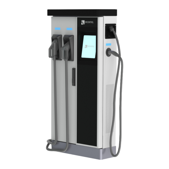
Features Overview 1- Cover 2- exit AC cable 3- AC light beacon 4- CHAdeMO connector 5- Unit air inlet 6- Power M. air outlet 7- D. front panel 8- D. rear panel 9- Handle 10- CHAdeMO holder 11- CCS holder 12- AC holder or 13- CCS light beacon 14- CHAdeMO light beacon... - Page 10 Raption 50 Series Instruction Manual Dimensions • Units specified in millimeters:...
-
Page 11: Status Led
Status LED Over each connector there is a beacon light, it indicates the state of charge in which the socket/connector is located. Colour Status Description Green Available The connector or socket is available to start a charging session Blue Charging The connector or socket is performing a charging session Cyan Booked... - Page 12 Raption 50 Series Instruction Manual Connectors The Charge Point is equipped with three connectors of different load; these can recharge a large range of vehicles: • AC (Mode 3): Type 2 tethered cable (63A/44kW) or Type 2 socket (32A/22kW)* • DC (Mode 4): CHAdeMO, Tethered cable, 3m. Until 125 A / 50 kW •...
- Page 13 Watch Out!! If your Charge Point is equipped with the ‘Mechanical connector locking’ accesory at DC holders is not possible to pull back the connectors from holders without first unlocking it. There are one label placed between the CHAdeMO and the CCS holders explaining Also there is one Led over each holder indicating the lock state: - Red >...
- Page 14 Raption 50 Series Instruction Manual The connectors will be delivered right in the moment than the user push over the ‘connector touching button’ when choose the option in the HMI screen:...
- Page 15 At the AC side for every Charge Point (It is not an optional device) there is a manual lock for keeping the connector, follow the indications shown on the label in order to remove the AC connector. 1- Push over the upper plastic button in order to release the connector. 2- Pull back the connector.
- Page 16 Raption 50 Series Instruction Manual General The first time the Charge Point is powered on, the system will take around 10 seconds for starting up, the screen will show next image: In the lower right corner, it shows the firmware version. After that 10 seconds have passed, the first screen that appears is the screensaver, Tap over this screen, and the HMI will skip to the next screen:...
-
Page 17: How To Use It
How to use it ? At this new screen, the Charge Point is asking for showing the identification card or touch the screen, as you can see there are two options. The first option, showing the identification card, is the option that will let to initiate a “charging session”... - Page 18 Raption 50 Series Instruction Manual Next screen will appear, press over your language’s flag: It is possible to choose between next languages: Catalan; German; English; Spanish; Finnish; French; Italian; Dutch; Norwegian; Polish; Russian; Swedish.
- Page 19 Starting a charging session - Once you have shown your identification card, the HMI will show next screen: Wait while Charge Point performs identification - If everything is correct and the user is authorized, the HMI will show next screen:...
- Page 20 Raption 50 Series Instruction Manual - Now, the user can choose the connector, always depending of the sort of vehicle that you have and if the connector status is available: At any time is possible to press over this button in order to go back to the “identification screen”.
- Page 21 2- Checking vehicle connection… Please wait - In a few seconds, the charging session will start and the HMI will show the charging process. Pressing over this button, the screen will go back to the “identification screen”.
- Page 22 Raption 50 Series Instruction Manual Special events starting a charge A - “Not authorized”: some Charge Points could be working under the supervision of the main management system, called Back Office. It can generate a whitelist in order to register new users, manage charging sessions, etc. If the user is not authorized, the HMI will show the following message: B - “Authorization failed”: if there is some communication problem with the Back Office right at the connecting time:...
- Page 23 C - “Not authorized, Concurrent charge”: in this case, the identifier is already involved in another charge transaction: D - “Not authorized, Authorization expired”: is possible that the back office has put deadline to your identification card and this date is already expired:...
- Page 24 Raption 50 Series Instruction Manual E - “Not authorized, Authorization blocked”: is possible that the back office has blocked temporarily your identification card. F – After the user has been properly authorized and just at the moment that has to choose the connector, the screen will show the connectors status, it could appear some problem.
- Page 25 G - Another issue that can occur is “Vehicle not detected”, unlock the connector, connect again and press over “Retry” button. H – Almost all vehicles cannot charge if the shift lever is not in parking mode position. This situation can be detected for the Charge Point and it will be displayed by HMI as “Please, check vehicle shift position, put in parking mode”, after pressing over “Retry”...
- Page 26 Raption 50 Series Instruction Manual I – Is possible that the problem than appears is not a concrete one, the HMI will show next screen, press over “Retry” button.
- Page 27 Stopping a charging session - The HMI is showing the charging process and next message “Show your identification to stop”, the session can be stopped by the same user that has started it. - After showing your identification card, the Charge Point will allow you to stop the charging session, press over the “Stop”...
- Page 28 Raption 50 Series Instruction Manual - Once you have stopped the charging session, the HMI will show the summary screen, press over the “Exit” touch button and disconnect your vehicle:...
- Page 29 Charging information Depending of the sort of charging that it has been done either AC or DC, the HMI screen can show different process information. There are different information for AC (mode 3), DC (CCS) and DC (CHAdeMO); the following images show the basic charging process information. 1 —...
- Page 30 Raption 50 Series Instruction Manual 2 — C H A R G I N G D C ( C C S ) 1- Language button: pressing over this button it is possible to change the HMI language. 2- Analog process indicator: at first moment it is red, as the vehicle is charging it will change to green, passing before for orange.
- Page 31 3 — C H A R G I N G D C ( C H A M O ) 1- Language button: pressing over this button it is possible to change the HMI language. 2- Analog process indicator: at first moment it is red, as the vehicle is charging it will change to green, passing before for orange.
- Page 32 Raption 50 Series Instruction Manual Charging summary The following image appears when EVs have finished charging or the session has been interrupted by the user. There are different summary screen, depending of you are charging on AC (mode 3) or DC (CCS / CHAdeMO). 1 —...
- Page 33 2 — S U M M A R Y S C R E E N F O R D C ( C C S / C H A M O ) 1- Language button: pressing over this button it is possible to change the HMI language.
- Page 34 Raption 50 Series Instruction Manual Emergency button If for any reason the Emergency button has been pressed, the beacon lights are in red and it will not be possible to do any charge. All the power modules will shut down in order to protect the user and the own Charge Point.
- Page 35 2 — S U M M A R Y S C R E E N F O R D C ( C C S / C H A M O ) 1- Language button: pressing over this button it is possible to change the HMI language.
- Page 36 Raption 50 Series Instruction Manual Connectors status The HMI screen shows a different symbols over the connector pictures, as you can see below: - It means that there is not any problem in this connector and is ready for use. - This connector is out of service for any technical reason.
- Page 37 - The user cannot use this connector because another user is already using it. - This connector has been reserved and only will be able to use per the user that has made the reserve. NOTE: if the user that has reserved the Charge Point is yourself the charging session will start normally, if not, the Charge Point will not be able to charge until the date and time displayed have expired.
- Page 38 Raption 50 Series Instruction Manual Consulting the connectors status It is possible to press over each connector picture to get more information about the status: 1 — C O N N E C T O R A B L E 2 —...
- Page 39 3 — C O N N E C T O R D I S A B L E 4 — C O N N E C T O R I N U S E...
- Page 40 Raption 50 Series Instruction Manual 5 — C O N N E C T O R R E S E R V E D 6 — C O N N E C T O R B L O C K E D P E R R E S E R V E D...
- Page 41 7 — C O N N E C T O R B L O C K E D P E R C H A R G I N G...
- Page 42 Raption 50 Series Instruction Manual Errors The Charge Point can report about different sort of errors, it can be from different parts or devices from it. When the “error screen” appears, the “Information” touch button has to be pressed in order to see the error message, as you can see below:...
- Page 44 Raption 50 Series Instruction Manual Introduction The Charge Point can be configured and monitored to establish owner preferences or specific setup using integrated Ethernet communication port allocated in HMI screen device. Once service PC is configured as bellow procedure and connection established with the Charge Point, direct access to the main setup page will be showed.
- Page 45 - Computer running Microsoft Windows, at least Windows XP . - UTP Cable (Crossover recommended) - IPSetup.exe (*) - CirCarLife Scada Client (*) (*) In order to get the software needed, you can download it from http://circontrol. com/downloads/ or contact with ps-support@circontrol.com...
- Page 46 Raption 50 Series Instruction Manual Network topology Connecting the service PC with Charge Point needs to be done with static IP address and TCP/IP v4 protocol. Next section shows how to do this configuration. Below image shows Ethernet connection topology and the IP addresses used in this guide as example. For laptop >...
- Page 47 LAN connection procedure This section provides a step-by-step guide to connect the service PC to the Charge Point in order to see real-time status. 1- Click on the network icon next to the clock of the taskbar, and Click on > “Open Network and Sharing Center”...
- Page 48 Raption 50 Series Instruction Manual 3- Make right click on > “Local Area Connection” and then click on > “Properties” 4- Select “Internet Protocol Version 4 (TCP/IP)” option and click on > “Properties”...
- Page 49 5- Setup IP address and subnet mask like as shown here below and click “OK” twice to complete the assigning IP address process to the computer. 6- Execute > IPSetup.exe on the service PC...
- Page 50 Raption 50 Series Instruction Manual 7- Enter the following parameters and click on > “Configure” • MAC of the Charge Point (see label on the screen) • IP address: i.e.(192.168.1.11) • Netmask: i.e. (255.255.255.0) • Gateway: leave default settings. 8- Wait 30 seconds approximately until the process is complete.
- Page 51 9- The process will complete when the following message appears, click on > “OK” 10- If the message shown is the next one, check the following parameters and click on > “OK” • Check IP address entered. • Check the MAC of the device entered. •...
- Page 52 Raption 50 Series Instruction Manual Setup Webpage Setup webpage allows managing networking setup, upgrading devices and other options. Once the service PC is already connected with Charge Point, it is possible to go inside de Setup Webpage throug the IP. In the example shown above, it has been set 192.168.1.11.
- Page 53 Dashboard OVERVIEW As a relevant information, the ‘Summary’ shows: Value Description Firmware version Version of the firmware currently working in the Charge Point MAC Address Identifier of the network card of the Charge Point...
- Page 54 Raption 50 Series Instruction Manual DEVICES STATUS As a relevant information, the ‘Devices Status’ shows: Value Description Device name Name of the devices inside the Charge Point OK: online Status NOT OK: offline...
- Page 55 SYSTEM STATUS - The information shown in this section is basically relative to the state of the PC of the Charge Point, it is necessary for the technical service staff but does not show any information regarding the external connection of the Charge Point or regard to the charging session.
- Page 56 Raption 50 Series Instruction Manual DRIVERS - The information shown in this section is regard to the drivers that the Charge Point needs in order to recognize the different devices inside the Charge Point, such as the meters, the mode 3, the RFID reader, etc.
- Page 57 REPOSITORY SOURCES - The information shown in this section is basically related to the internal behavior of the Charge Point, it is necessary for the technical service staff but does not show any information about the external connection of the Charge Point or with respect to the charging session.
- Page 58 Raption 50 Series Instruction Manual SYSTEM LOGS - The logs shown in this section are automatically produced by the Charge Point, it is a detailed list of the charging session, system performance, or user activities. This logs are created since Charge Point is powered On. If Charge Point is restarted this logs are erased and immediately is created a new one.
- Page 59 Network This section provides basic configuration of the network parameters. Clicking over the ‘Network’ tab, next image will appear. Next, we will explain the different sections of the 'Network' Value Description Hostname Name of the Charge Point on the network...
- Page 60 Raption 50 Series Instruction Manual Value Description • Local address: select this option if the OCPP central system is connected to the same private network than the charge point is already connected. It is assigned to the Ethernet Port. • Static address: select this option if the external modem/router is different than listed below.
- Page 61 Security This section provides basic configuration of the security parameters. Avoiding unauthorised access to the Setup Webpage. All parameters are disable from factory settings. Clicking over the ‘Security’ tab, next image will appear. Next, we will explain the different sections of the 'Security' Value Description Authentication...
- Page 62 Raption 50 Series Instruction Manual Time This section allows setting the time and region time for the Charge Point. Clicking over the ‘Time’ tab, next image will appear. Next, we will explain the different sections of the 'Time' Value Description Time Zone Select the regional time for the Charge Point according to the location...
- Page 63 Integrations Clicking over the ‘Integrations’ tab, next image will appear. Note: The integration of the Charge Point deserves a separate chapter. In the next chapter number 5 we will explain how to integrate OCPP.
- Page 64 Raption 50 Series Instruction Manual Services The main opcion at this section allows to change the HMI language and also make a Grid test as well as setting a password. Clicking over the ‘Services’ tab, next image will appear. Next, we will explain the different sections of the 'Services' Value Description Grid Test...
- Page 65 Firmware Through ‘Firmware’ tab, the Charge Point firmware can be upgraded remotely. The upgrading firmware is suplly for CIRCONTROL Post Sales Support department. Clicking over the ‘Select File’ tab, a new pop up window will be open in order to choose the upgrading file.
- Page 66 With this protocol it is possible to connect any central system with any charge point, regardless of the vendor. Follow next steps in order to configure the OCPP in the Circontrol Charge Points.
-
Page 67: Ocpp Integrations
OCPP Integrations Previous requirements Check following steps in order to ensure the correct function of OCPP : At ‘Network’ tab Public Address Manager establishes where the Charge Point must obtain the public IP address in order to send it later to the backend. Different values can be selected in the ‘Address Type’... - Page 68 Raption 50 Series Instruction Manual At ‘Integrations’ tab Charge Point supports different versions of OCPP but only one can be enabled at the same time. Go back to setup web page and click on the ‘Integrations’ tab, choose the option selected under ‘Available integrations’...
- Page 69 Starting up configuration Setup Page Once you have chosen your OCPP option at the previous step, a link appears allowing access to the OCPP configuration. Please, click on the link button as shown in the picture: New tabs are opened to show OCPP Settings. First time is running the integration selected on the charge point, it starts as configuration mode and all fields are empty.
- Page 70 Raption 50 Series Instruction Manual At ‘Charge Box’ tab Check Charge Box Identity and the incoming ports according to the backend policies, please contact to the Central System to get the configuration parameters: Value Description Charge Point identifier Public IP timeout Maximum waiting time to obtain the public IP address of the 3G modem OCPP Internal Incoming listening port for remote request (internal)
- Page 71 At ‘Central system’ tab Allows the Charge Point to know where the central system is hosted to notify all the requests. Check Central System URL according to the backend policies, please contact to the Value Description ID Tag Endianness Storage type for system data Host URL URL address of the central system Authentication...
- Page 72 Raption 50 Series Instruction Manual At ‘OCPP Settings’ tab Check OCPP Settings according to the backend policies, please contact to the Central System to get the configuration parameters: Note: If any Authentication has been set at the previous steps, the system is going to ask for this: Before making any changes read following table and set each option according to your backend provider.
- Page 73 Value Description Yes: local list of authorized users -> Enabled Use local white-list No: local list of authorized users -> Disabled Local: ID authorization has first place on the local white- -list. If the user does not exist locally, then in second place backend is asked to obtain the authorization.
- Page 74 Raption 50 Series Instruction Manual Value Description Yes: Synchronization of date and time -> Enabled. No: Synchronization of date and time -> Disabled. Use OCPP time synchronization NOTE: Date and Time is sent from backend on each heartbeat response. Yes: Compress messages between Charge point and backend ->...
- Page 75 Value Description Yes: Stop existing charge transaction after response from backend (StartTransaction.conf) when user has Stop charge if already involved in another transaction. StartTransaction replies No: Charge transaction does not stops even if backend ConcurrentTx rejects the user. (StartTransaction.conf) NOTE: Set this option according to your backend system. Yes: Charge point sends an authorization request before starting a new remote charge transaction request.
- Page 76 Raption 50 Series Instruction Manual When done, please do not forget to save changes using save button in the upper right bar: Please, wait until the new configuration is being applied to the Charge Point. A message is displayed informing the progress:...
- Page 77 Checking configuration After applying new settings, please go to next URL from charge point in order to check properly connection from the integration chosen: http://<IP>/services/cpi/log?app=ocpp1.5 Look especially for the following messages: If “CB boot notification: success” appears then charge point is properly connected to the back-end.
- Page 78 Raption 50 Series Instruction Manual This section describes how to install the SIM card into the unit’s 3G modem. 1 — 3 G M O D E M L O C AT I O N The modem is installed inside the unit and the antenna is fixed outside, right on the roof of the unit.
-
Page 79: 3G Communications
Communications 2 — M O D E M O V E R V I E W The 3G modem installed from factory in the unit is: Sierra Wireless AirLink LS300 This device allows to the Charge Point connects over 3G networks to remotely view or manage the Charge Point status. - Page 80 Raption 50 Series Instruction Manual 4 — M O D E M C O N F I G U R AT I O N Plug again the power supply for the modem. NOTE: After plugging back the modem, it can take until 5 minutes to respond. 3G modem configuration is performed using the Ethernet interface.
- Page 81 Steps: 1- Open a web browser in the computer and enter http://192.168.13.31:9191. Wait until ACE manager login screen appears. user’ 12345 ’. Do not change the Default username is ‘ and default password is ‘ default credentials; the Charge Point requires consulting information from the 3G modem.
- Page 82 Raption 50 Series Instruction Manual 3- Once clicking over ‘WAN/Cellular’ tab, introduce the ‘APN’ provided by the SIM’s company. In case of ‘User ID’ and ‘Password’ are required too, it has to be added in the ‘Advanced’ section. Make click over ‘Apply’ tab in order to save. 4- In the ‘Security’...
- Page 83 Fill each field according to next picture: Remember to ‘Apply’ the changes when finish. 5- Click over ‘Reboot’ button and wait for 3-4 minutes. After that, the modem should have found an IP. Check it in the ‘Status’ tab. - Connect the modem to the unit. If the process has been done properly, we should have remote access to the unit using the IP from the step before.
- Page 84 Raption 50 Series Instruction Manual GENERAL DATA Display LCD Multi-language touch screen Light beacon RGB Colour indicator ISO / IEC 14443A/B MIFARE Classic/Desfire EV1 RFID reader ISO 18092 / ECMA-340 NFC 13.56MHz IEC-61851; IEC-62196; CE; CHAdeMO Certified; Compliance CCS (DIN 70121) MECHANICAL DATA Enclosure rating IP54 / IK10...
-
Page 85: Technical Data
Technical Data CONNECTIVITY Ethernet 10/100BaseTX (TCP-IP) Cellular Modem 3G / GPRS / GSM * Interface protocol OCPP ELECTRICAL DATA Power supply 3P+N+PE Voltage range 400 VAC +/- 10% Power factor > 0.98 Efficiency 95 % at nominal output power Standby consumption 38 W <... - Page 86 Raption 50 Series Instruction Manual MODEL SPECIFICATIONS MODELS CCS CHA T2C63 CCS CHA T2S32 CCS CHA CCS T2S32 Maximum AC 138 A 108 A 76 A 108 A input current Required power supply 96 KVA 75 KVA 53 KVA 75 KVA...
- Page 87 MODEL SPECIFICATIONS MODELS CHA T2S32 Maximum AC 108 A 76 A 76 A input current Required power supply 75 KVA 53 KVA 53 KVA capacity Maximum DC: 50 kW DC: 50 kW DC: 50 kW output power AC: 22 kW Output voltage DC: 50-500 VDC DC: 50-500 VDC...
- Page 88 Raption 50 Series Instruction Manual...
-
Page 89: Need Help
Need help? In case of any query or need further information, please contact our Post-Sales Department ps-support@circontrol.com circontrol.com (+34) 937 362 940 (+34) 937 362 941... - Page 90 CIRCONTROL Raption 50 Series INSTRUCTION MANUAL A comprehensive guide on how to use and configure your Raption 50 Charge Point. V1.1, August edition 2017 CIRCONTROL S.A. - ALL RIGHTS RESERVED...
Need help?
Do you have a question about the CCS CHA T2C63 and is the answer not in the manual?
Questions and answers