Table of Contents
Advertisement
Quick Links
READ AND SAVE THESE INSTRUCTIONS
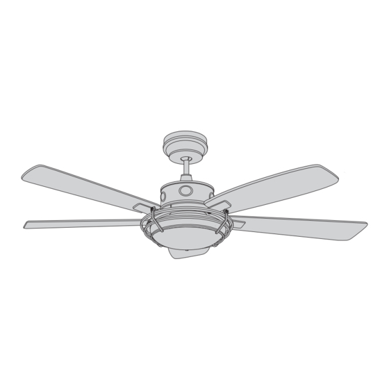
54" Wet Location Ceiling Fan
CF630ORB00 -
CF630SW00 -
CF630VS00 -
Questions, problems, missing parts: Before returning to the store call
Emerson Electric Customer Service 8 a.m. - 6 p.m., Eastern, Monday-Friday
Part No. F40BP75210000
Revision: 170213
ROCKPOINTE
Owner's Manual
Model Numbers
Vintage Steel
Net Weight:
1-800-654-3545
www.emersonfans.com
Oil Rubbed Bronze
Satin White
28.8
Lbs.
....
™
• Español - página 31
Form No. BP7521
ETL Model No.: CF630
Advertisement
Table of Contents

Related Manuals for Emerson ROCKPOINTE CF630ORB00


Summary of Contents for Emerson ROCKPOINTE CF630ORB00
- Page 1 Vintage Steel 28.8 Net Weight: Lbs. Questions, problems, missing parts: Before returning to the store call Emerson Electric Customer Service 8 a.m. - 6 p.m., Eastern, Monday-Friday 1-800-654-3545 • Español - página 31 Part No. F40BP75210000 Form No. BP7521 www.emersonfans.com Revision: 170213 ETL Model No.: CF630...
-
Page 2: Table Of Contents
1. To avoid possible shock, be sure electricity is turned Electric Co. Substitution of parts or accessories not off at the fuse box before wiring, and do not operate designated for use with this product by Emerson could fan without blades. result in personal injury or property damage. -
Page 3: Unpacking Instructions
Emerson Electric Co. Substitution of parts or Lower Housing accessories not designated for use with this product Light Kit Housing Assembly by Emerson Electric Co. could result in personal injury or property damage. Decorative Grill Glass Shade Fan Blade Flanges... -
Page 4: Tools Needed For Assembly
Wiring outlet box and box connectors must be of type required by the local code. The minimum wire would be a 3-conductor (2-wire with ground) of following size: Your Emerson Ceiling Fan comes supplied with a RCFP Receiver and SW406 Wall Control. This system Installed Wire Length Wire Size A.W.G. -
Page 5: Ceiling Fan Assembly
3. Ceiling Fan Assembly WARNING Disconnect electrical power to the branch circuit at the Circuit Breaker or Main Fuse Box before attempting to Turning off wall switch is not sufficient. To avoid possible electrical shock, be sure electricity is turned install the Ceiling Fan on the Outlet Box. -
Page 6: Ceiling Fan Assembly
3. Ceiling Fan Assembly (Continued) Loosen the two Set Screws in the Motor Coupler for installation of the Downrod (Figure 3). Seat the 4.5” Downrod in the Motor Coupler (Figure 3). Rotate and align the Downrod holes with all the holes in 4.5"... - Page 7 3. Ceiling Fan Assembly (Continued) Place the Ceiling Cover over the 4.5” Downrod and rest 4.5" DOWNROD it on the Coupler Cover (Figure 6). CEILING COVER Be sure both the Ceiling Cover and the Coupler Cover are oriented correctly as in Figure 6. COUPLER COVER Figure 6...
- Page 8 3. Ceiling Fan Assembly (Continued) 3.10 Carefully turn the partially assembled Ceiling Fan over PARTIALLY REMOVE & DISCARD and place it on the styrofoam for final preparation ASSEMBLED SHIPPING SPACERS & (Figure 9). CEILING FAN ATTACHMENT SCREWS (5) Remove the five Shipping Spacers and the Spacer Attachment Screws from the Motor before installation of blade assemblies (Figure 9).
- Page 9 3. Ceiling Fan Assembly (Continued) 3.12 Loosely attach one Blade/Flange Assembly to the 1/4-20 x 9/16" PAN HEAD Motor Hub by securing the two 1/4-20 x 9/16” Pan SCREW w/LOCKWASHER (2 per blade/flange assembly) Head Screws with Lockwashers (supplied) (Figure 11). BLADE/FLANGE ASSEMBLY Make sure the screws are NOT tightened.
-
Page 10: How To Hang Your Ceiling Fan
3. Ceiling Fan Assembly (Continued) 3.14 Connect the White Wire from the Light Kit Housing Assembly to the White Wire from the Fan Motor Assembly (Figure 13). LIGHT KIT HOUSING ASSEMBLY BLACK WIRE Connect the Black Wire from the Light Kit Housing LIGHT KIT HOUSING Assembly to the Black Wire from the Fan Motor ASSEMBLY WHITE WIRE... -
Page 11: How To Hang Your Ceiling Fan
4. How to Hang Your Ceiling Fan WARNING CEILING The fan must be hung with at least 7' of clearance from floor to blades (Figure 15). WARNING Turning off wall switch is not sufficient. To avoid possible electrical shock, be sure electricity is turned off at the main fuse box before wiring. - Page 12 4. How to Hang Your Ceiling Fan (Continued) Securely attach the Hanger Bracket to the Outlet Box using the two Screws supplied with the Outlet Box (Figure 17). OUTLET BOX WARNING TWO SCREWS SUPPLIED WITH Hanger bracket must seat firmly against outlet box. OUTLET BOX HANGER BRACKET If the outlet box is recessed, remove wall board until...
-
Page 13: How To Wire Your Ceiling Fan
Emerson Electric Co. Substitution of parts or WARNING accessories not designated for use with this product by Emerson Electric Co. could result in personal injury Turning off wall switch is not sufficient. To avoid or property damage. possible electrical shock, be sure electricity is turned off at the main fuse box before wiring. - Page 14 5. How to Wire Your Ceiling Fan (Continued) RECEIVER Securely connect the Supply White (neutral) Wire to the WHITE WIRE Receiver White (AC IN N) Wire using the Wire Connector (supplied) (Figure 21). SUPPLY WHITE WIRE Securely connect the Fan Motor White Wire to the (NEUTRAL) Receiver White (TO MOTOR N) Wire using the Wire Connector (supplied) (Figure 21).
- Page 15 5. How to Wire Your Ceiling Fan (Continued) After connections have been made, turn wires upward and carefully push wires into the outlet box, with the OUTLET BOX ANTENNE white and green wires on one side of the outlet box and WIRE position the black and blue wires on the other side of SLIDE RECEIVER...
-
Page 16: Final Assembly
6. Final Assembly Install a 13-Watt (maximum) CFL E26 Medium Base Bulb (supplied) in each of the three Light Kit Housing Assembly Sockets (Figure 25). WARNING To avoid the risk of fire, use 13-Watt bulbs (maximum). LIGHT KIT HOUSING ASSEMBLY SOCKETS (3) 13-WATT CFL MEDIUM BASE BULBS (3) Figure 25... - Page 17 KNOBS (2) Figure 29 You have now completed the complete assembly of your new ceiling fan. Please call Emerson technical support 1-800-654-3545 if you have any questions about installation and operation of this ceiling fan. emersonfans.com Please contact 1-800-654-3545 for further assistance...
-
Page 18: Wall Control Procedure
Code switches in the SW406 Wall Control Transmitter may be set in 32 different positions. If your fan and light Your Emerson Ceiling Fan/Light Control consists of turn on and off without using your control, you may be SW406 Wall Mounted Transmitter and a Receiver getting interference from other remote units such as located inside the motor assembly. -
Page 19: Wall Control Installation
8. Wall Control Installation SINGLE-POLE INSTALLATION WARNING CAUTION: To reduce the risk of electrical shock, Turning off wall switch is not sufficient. To avoid disconnect the electrical supply circuit before possible electrical shock, be sure electricity is turned installing the fan, light kit or receiver. off at the main fuse or circuit breaker box before wiring. -
Page 20: Wall Control Installation
8. Wall Control Installation (Continued) Before installing the SW406 Wall Control, place the SCREWS (2) SW406 FAN/LIGHT SW406 Wall Control in “OFF” mode by pushing WALL CONTROL WALL “ON/OFF” switch to the “OFF” position..Connect the SW406 Wall Control Black Wire with the Yellow Label marked “To Power Supply”... -
Page 21: Warning
8. Wall Control Installation (Continued) 3-WAY INSTALLATION (One fan controlled by two different SW406 wall SW406 SECOND SW406 FAN/LIGHT WALL CONTROL ..controls) (See Figures 33 and 34.) WALL PURCHASED CONTROL SEPARATELY WARNING GROUND GROUND BLACK Turning off wall switch is not sufficient. To avoid possible electrical shock, be sure electricity is turned LOAD TRAVELER... -
Page 22: Warning
8. Wall Control Installation (Continued) 3-WAY WIRING DIAGRAM: WARNING NOTE: Retrofit 3-way installations are likely to include two traveler wires between the two wall Check to see that all connections are tight and that no bare wires are visible at the wire connectors. boxes. -
Page 23: Programming The Receiver Operating Frequency
9. Programming the Receiver Operating Frequency PROGRAMMING THE RECEIVER OPERATING FREQUENCY If programming is unsuccessful, retry the above IMPORTANT: Ceiling fan blades MUST be installed instructions after cycling the SW406 Wall Control before high speed conditioning can begin. ON/OFF switch to restart the 1 minute programming time period. -
Page 24: Using Your Ceiling Fan
10. Using Your Ceiling Fan USING YOUR CEILING FAN WARNING Your SW406 Wall Control has full control of your fan Fan installation must be completed, including the installation of the fan blades, before testing the SW406 and light. Wall Control. NOTE: Prior to operation of the ceiling fan and light from the wall control, set the fan speed to HIGH ( .. -
Page 25: Maintenance
emersonfans.com Please contact 1-800-654-3545 for further assistance ETL Model No.: CF630... -
Page 26: Repair Parts
14. Repair Parts HARDWARE BAG (Not Shown) ....ETL Model No.: CF630... -
Page 27: Repair Parts
14. Repair Parts Listing Model Numbers Description CF630RB00 CF630SW00 CF630VS00 Hanger Ball Assembly, Consisting of: 761655-32 761655-92 761655-93 Hanger Bracket (1) — — — Hanger Ball (1) — — — 4.5” Downrod Assembly (1) — — — Hardware Bag Containing: 764834-BLXS 764834-SWS 764834-BLXS... -
Page 28: Troubleshooting
15. Troubleshooting WARNING FOR YOUR OWN SAFETY TURN OFF POWER AT FUSE BOX OR CIRCUIT BREAKER BEFORE TROUBLESHOOTING YOUR FAN. TROUBLE PROBABLE CAUSE SUGGESTED REMEDY 1. Fan will not start. 1. Reversing switch in neutral position. 1. Make sure reversing switch position is all the way to one side. -
Page 29: Ceiling Fan Limited Warranty
Emerson Ceiling Fan. Once we have processed your return authorization request, we will provide you with a postage paid return label which should be affixed to the Emerson Ceiling Fan package you ship to the address listed at the end of this limited warranty. The return label will be sent to the mailing address you provide to us by phone. - Page 30 You should record this data above and keep it in a safe place for future use. Air Comfort Products DIVISION OF EMERSON ELECTRIC CO. 8100 W. Florissant • St. Louis, MO 63136 Questions, problems, missing parts: Before returning to the store call Emerson Electric Customer Service 8 a.m.
Need help?
Do you have a question about the ROCKPOINTE CF630ORB00 and is the answer not in the manual?
Questions and answers