Advertisement
BPC370-BW Installation Guide
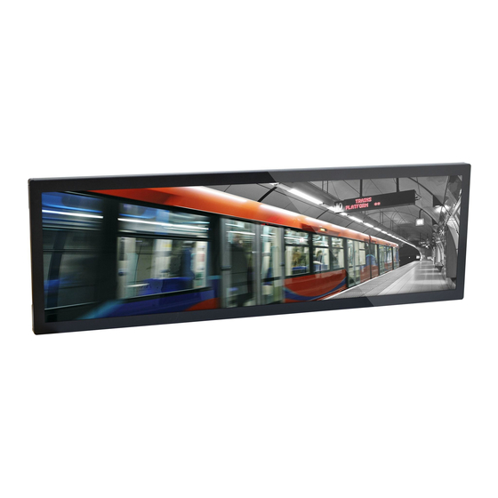
• One 37" bar-type panel PC
• 1 DVD disk includes:
- Manual
DFI reserves the right to change the specifi cations at any time prior to
the product's release. For the latest revision and more details of the
installation procedure, please refer to the user's manual on the website.
Package Contents
www.dfi .com
1
Advertisement
Table of Contents

Subscribe to Our Youtube Channel
Related Manuals for DFI BPC370-BW


Summary of Contents for DFI BPC370-BW
-
Page 1: Package Contents
• 1 DVD disk includes: - Manual DFI reserves the right to change the specifi cations at any time prior to the product's release. For the latest revision and more details of the installation procedure, please refer to the user's manual on the website. - Page 2 Panel Power button COM 1 Antenna hole (RS232) Left View DP++ LAN 1/LAN 2 COM 2 USB 3.0 (RS232) Right View AC-in...
- Page 3 Removing the Chassis Cover 1. Make sure the system and all other peripheral devices connected to it have been powered-off. 2. Disconnect all power cords and cables. 3. The 12 mounting screws on the rear side of the system are used to secure the cover to the chassis.
- Page 4 Installing a Mini PCIe Card The system board is equipped with 2 Mini PCIe slots: one full-size and one half-size slots. Here we will demonstrate the installation of the full-size Mini PCIe card with the mSATA interface. 1. Grasp the Mini PCIe card by its edges and align the notch in the connector of the PCIe card with the notch in the connector on the system board.
-
Page 5: Mounting The Device
Mounting the Device Vesa mount The VESA-mount specifications for this device is 400 x 200 (mm). Please use a compatible VESA-mount kit that can sustain the weight and size of this device. Please refer to the following illustration for screw-hole positions. - Page 6 Board Layout and Jumper Settings 4-pin Right Angle Backlight Power Select (JP10) DC-in Front Audio SMBus Auto Power-on Realtek Select (JP6) ALC888 4-pin Vertical Type (optional) Front Panel LAN 1 RT8175A Panel Power Intel Select (JP8) Digital I/O WGI211AT RT5041A RT8175A LAN 2 RT8175A...
Need help?
Do you have a question about the BPC370-BW and is the answer not in the manual?
Questions and answers