Sign In
Upload
Manuals
Brands
Intel Manuals
Server
S2600CW
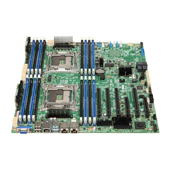
Intel S2600CW Manuals
Manuals and User Guides for Intel S2600CW. We have
2
Intel S2600CW manuals available for free PDF download: Technical Product Specification, Spares/Accessories List And Configuration Manual
Intel S2600CW Technical Product Specification (210 pages)
Brand:
Intel
| Category:
Server Board
| Size: 6 MB
Table of Contents
Table of Contents
4
1 Introduction
15
Chapter Outline
15
Server Board Use Disclaimer
16
2 Intel® Server Board S2600CW Overview
17
Intel® Server Board S2600CW Feature Set
17
Table 1. Intel® Server Board S2600CW Feature Set
17
Server Board Layout
19
Figure 1. Intel Server Board S2600CW2SR and S2600CWTSR
19
Figure 2. Intel Server Board S2600CW2R and S2600CWTR
20
Figure 3. Connector and Component Layout
21
Server Board Connector and Component Layout
21
Figure 4. Mounting Hole Locations (1 of 2)
22
Server Board Mechanical Drawings
22
Figure 5. Mounting Hole Locations (2 of 2)
23
Figure 6. Major Connector Pin-1 Locations (1 of 2)
24
Figure 7. Major Connector Pin-1 Locations (2 of 2)
25
Figure 8. Primary Side Card-Side Keep-Out Zone
26
Figure 9. Second Side Keep-Out Zone
27
Figure 10. Rear I/O Layout of Intel
28
Server Board Rear I/O Layout
28
3 Intel® Server Board S2600CW Functional Architecture
29
Figure 11. Intel Server Board S2600CW2R/S2600CWTR Functional Block Diagram
29
Processor Support
30
Processor Socket Assembly
30
Figure 12. Intel Server Board S2600CW2SR/S2600CWTSR Functional Block Diagram
30
Processor Population Rules
31
Figure 13. Processor Socket Assembly
31
Table 2. Mixed Processor Configurations
32
Processor Functions Overview
34
Intel® Virtualization Technology (Intel® VT) for Intel® 64 and IA-32 Intel® Architecture (Intel® VT-X)
35
Intel® Virtualization Technology for Directed I/O (Intel® VT-D)
35
Intel® Trusted Execution Technology for Servers (Intel® TXT)
36
Execute Disable
36
Advanced Encryption Standard (AES)
36
Intel® Hyper-Threading Technology
36
Intel® Turbo Boost Technology
36
Enhanced Intel Speedstep® Technology
37
Intel® Advanced Vector Extensions 2 (Intel® AVX2)
37
Intel® Node Manager 3.0
37
Intel® Secure Key
38
Intel® os Guard
38
Trusted Platform Module (TPM)
38
Integrated Memory Controller (IMC) and Memory Subsystem
38
Figure 14. Memory Subsystem for Intel
38
Supported Memory
39
Table 3. RDIMM Support
39
Memory Population Rules
40
Table 4. LRDIMM Support
40
Figure 15. Intel Server Board S2600CW DIMM Slot Layout
41
Effects of Memory Configuration on Memory Sizing
42
Publishing System Memory
43
RAS Features
43
3.3.6 Memory Initialization
44
System IO
48
PCI Express* Support
48
Pcie Enumeration and Allocation
49
Pcie Non-Transparent Bridge (NTB)
50
Pcie SSD Support
51
Serial ATA (SATA) Support
52
SATADOM Support
52
M.2/NGFF Support
53
Embedded SATA RAID Support
54
Serial Attached SCSI (SAS) Support
57
Integrated Megaraid Support
58
USB Support
59
Graphics Controller and Video Support
60
Table 6. Video Modes
60
Figure 16. BIOS Setup Utility - Video Configuration Options
63
Trusted Platform Module
65
Network Support
65
Figure 17. TPM Module
65
Table 7. External RJ45 NIC Port LED Definition
67
4 System Security
68
BIOS Setup Utility Security Option Configuration
68
BIOS Password Protection
69
Table 8. Setup Utility - Security Configuration Screen Fields
69
Trusted Platform Module (TPM) Support
71
TPM Security BIOS
71
Physical Presence
72
TPM Security Setup Options
72
Intel® Trusted Execution Technology
72
5 Intel® Server Board S2600CW Platform Management
74
Management Feature Set Overview
74
IPMI 2.0 Features Overview
74
Non-IPMI Features Overview
75
Platform Management Features and Functions
77
Power Subsystem
77
Advanced Configuration and Power Interface (ACPI)
77
Table 9. ACPI Power States
77
System Initialization
78
Watchdog Timer
79
System Event Log (SEL)
79
Sensor Monitoring
79
Sensor Scanning
79
Sensor Rearm Behavior
80
BIOS Event-Only Sensors
81
Margin Sensors
81
IPMI Watchdog Sensor
81
BMC Watchdog Sensor
81
BMC System Management Health Monitoring
81
VR Watchdog Timer
81
System Airflow Monitoring
82
Thermal Monitoring
82
Processor Sensors
85
Table 10. Processor Sensors
86
Table 11. Processor Status Sensor Implementation
86
Voltage Monitoring
88
Fan Monitoring
89
Standard Fan Management
91
Figure 18. High-Level Fan Speed Control Process
94
Power Management Bus (Pmbus*)
97
Power Supply Dynamic Redundancy Sensor
98
Component Fault LED Control
98
NMI (Diagnostic Interrupt) Sensor
99
LAN Leash Event Monitoring
99
Table 12. Component Fault Leds
99
Add-In Module Presence Sensor
100
CMOS Battery Monitoring
100
Embedded Web Server
100
Advanced Management Feature Support (RMM4 Lite)
102
Table 13. Basic and Advanced Server Management Features Overview
102
Table 5. Intel
102
Keyboard, Video, Mouse (KVM) Redirection
104
Performance
105
Remote Console
105
Availability
106
Force-Enter BIOS Setup
106
Media Redirection
106
Security
106
Usage
106
6 Intel® Intelligent Power Node Manager (NM) Support Overview
109
Hardware Requirements
109
Features
109
ME System Management Bus (Smbus*) Interface
110
Peci 3.0
110
NM "Discovery" OEM SDR
110
Smart/Clst
110
Dependencies on Pmbus*-Compliant Power Supply Support
111
7 Intel® Server Board S2600CW Connector/Header Locations and Pin-Outs
112
Power Connectors
112
Main Power Connector
112
CPU Power Connectors
112
Table 14. Main Power Connector Pin-Out
112
Table 15. CPU_1 Power Connector Pin-Out
112
Table 16. CPU_2 Power Connector Pin-Out
112
Front Panel Header and Connectors
113
Front Panel Header
113
Front Panel USB Connector
113
Table 17. Front Panel Header Pin-Out
113
On-Board Storage Connectors
114
SATA 6Gbps Connectors
114
Table 18. Front Panel USB 3.0 Connector Pin-Out
114
Table 19. SATA 6Gbps Connector Pin-Out
114
Table 20. Mini-SAS HD Connectors for SATA 6Gbps Pin-Out
114
SAS Connectors
115
HSBP I 2 C Header
115
HDD LED Header
115
Table 21. Mini-SAS HD Connectors for SAS 12Gbps Pin-Out
115
Table 22. HSBP I 2 C Header Pin-Out
115
Internal Type-A USB Connector
116
Internal Eusb SSD Header
116
M.2/NGFF Header
116
Table 23. HDD LED Header Pin-Out
116
Table 24. Type-A USB Connector Pin-Out
116
Table 25. Eusb SSD Header Pin-Out
116
Table 26. M.2/NGFF Header Pin-Out
116
Management and Security Connectors
117
RMM4 Lite Connector
117
Figure 19. Intel
117
TPM Connector
118
Pmbus* Connector
118
Chassis Intrusion Header
118
Table 27. RMM4 Lite Connector Pin-Out
118
Table 28. TPM Connector Pin-Out
118
Table 29. Pmbus* Connector Pin-Out
118
Table 30. Chassis Intrusion Header Pin-Out
118
IPMB Connector
119
FAN Connectors
119
System FAN Connectors
119
CPU FAN Connector
119
Table 31. IPMB Connector Pin-Out
119
Table 32. 6-Pin System FAN Connector Pin-Out
119
Table 33. 4-Pin System FAN Connector Pin-Out
119
Serial Port and Video Connectors
120
Serial Port Connector
120
Video Connector
120
Table 34. CPU FAN Connector Pin-Out
120
Table 35. Serial Port B Connector Pin-Out
120
Table 36. Video Connector Pin-Out
120
Pcie Riser Slot
121
Figure 20. Video Connector Pin-Out
121
8 Intel Server Board S2600CW Jumper Blocks
125
Figure 21. Jumper Blocks
125
Table 37. Server Board Jumpers
125
BIOS Default and Password Reset Usage Procedure
126
Set BIOS to Default (Clearing the CMOS)
126
Clearing the Password
126
Integrated BMC Force Update Procedure
127
ME Force Update Jumper
128
BIOS Recovery Jumper
129
9 Intel Light Guided Diagnostics
130
5-Volt Stand-By LED
130
Figure 22. 5-Volt Stand-By Status LED Location
130
Fan Fault Leds
131
Figure 23. Fan Fault Led's Location
131
DIMM Fault Leds
132
Figure 24. DIMM Fault Led's Location
132
System ID LED, System Status LED, and POST Code Diagnostic Leds
133
System ID LED
133
Figure 25. Location of System Status, System ID, and POST Code Diagnostic Leds
133
System Status LED
134
Table 38. System Status LED
134
POST Code Diagnostic Leds
135
Table 39. POST Code Diagnostic Leds
135
10 Power Supply Specification Guidelines
136
10.1 Power System Options Overview
136
10.2 750-W Power Supply
136
Mechanical Overview
136
Figure 26. 750-W Power Supply Outline Drawing
136
Table 40. DC Output Connector
137
Table 41. LED Characteristics
138
Table 42. Power Supply LED Functionality
138
Table 43. Environmental Requirements
138
AC Input Requirements
139
Table 44. Power Factor Requirements for Computer Servers
139
Table 45. AC Input Voltage Range
139
Table 46. AC Line Holdup Time
140
Table 47. AC Line Sag Transient Performance
140
Efficiency
141
DC Output Specification
141
Table 48. AC Line Surge Transient Performance
141
Table 49. Silver Efficiency Requirement
141
Table 50. Minimum Load Ratings
141
Table 51. Voltage Regulation Limits
142
Table 52. Transient Load Requirements
142
Table 53. Capacitive Loading Conditions
142
Figure 27. Differential Noise Test Setup
144
Table 54. Ripples and Noise
144
Table 55. Timing Requirements
144
Protection Circuits
145
Figure 28. Turn On/Off Timing (Power Supply Signals)
145
Control and Indicator Functions
146
Table 56. over Current Protection
146
Table 57. over Voltage Protection (OVP) Limits
146
Figure 29. PSON# Required Signal Characteristic
147
Table 58. PSON# Signal Characteristic
147
Table 59. PWOK Signal Characteristics
148
Table 60. Smbalert# Signal Characteristics
148
Thermal CLST
149
Power Supply Diagnostic "Black Box
149
Firmware Uploader
149
Higer Power Common Redundant Power Distribution Board (PDB)
150
Mechanical Overview
150
Figure 30. Outline Drawing
150
DC Output Specification
151
Figure 31. Airflow Diagram
151
Table 61. Thermal Requirements
151
Table 62. Input Connector and Pin Assignment
152
Table 63. PDB Cable Length
152
Table 64. P1 Baseboard Power Connector
153
Table 65. P0 Processor Power Connector
154
Table 66. P1 Processor Power Connector
154
Table 67. Power Signal Connector
154
Table 68. P12 12V Connectors
155
Table 69. P13-P16 12V Connectors
155
Table 70. P8, P9 Legacy Peripheral Power Connectors
155
Table 71. P7, P10, P11 Legacy Peripheral Power Connectors
155
Table 72. SATA Peripheral Power Connectors
155
Table 73. Remote Sense Connection Points
156
Table 74. Remote Sense Requirements
156
Table 75. 12V Rail Distribution
156
Table 76. Hard Drive 12V Rail Configuration Options
157
Table 77. DC/DC Converters Load Ratings
157
Table 78. 5VSB Loading
158
Table 79. Voltage Regulation Limits
158
Table 80. Transient Load Requirements
158
Table 81. Capacitive Loading Conditions
159
Table 82. Ripple and Noise
159
Figure 32. Differential Noise Test Setup
160
Table 83. Output Voltage Timing
160
Protection Circuits
161
Table 84. PDB over Current Protection Limits/240Va Protection
161
Table 85. over Voltage Protection (OVP) Limits
161
PWOK (Power OK) Signal
162
PSON Signal
162
Pmbus
162
Table 86. System PWOK Requirements
162
Table 87. PDB Addressing
162
11 Design and Environmental Specifications
163
Intel Server Board S2600CW Design Specifications
163
Table 88.Server Board Design Specifications
163
11.2 Mtbf
164
Table 89. MTBF Estimate
164
Appendix A: Integration and Usage Tips
165
Appendix B: Compatible Intel Server Chassis
166
Table 90. Compatible Intel
166
Appendix C: BMC Sensor Tables
167
Table 91. Integrated BMC Core Sensors
169
Appendix D: Platform Specific BMC Appendix
185
Appendix E: POST Code Diagnostic LED Decoder
190
Figure 33. POST Code Diagnostic LED Decoder
190
Table 92. POST Progress Code LED Example
191
Table 93. POST Progress Codes
191
Table 94. MRC Progress Codes
196
Table 95. MRC Fatal Error Codes
197
Appendix F: POST Error Code
198
Table 96. POST Error Codes and Messages
198
Table 97. POST Error Beep Codes
203
Table 98. Integrated BMC Beep Codes
203
Appendix G: Statement of Volatility
205
Glossary
207
Reference Documents
210
Advertisement
Intel S2600CW Spares/Accessories List And Configuration Manual (54 pages)
Server Board/Chassis
Brand:
Intel
| Category:
Server
| Size: 2 MB
Table of Contents
Document Revision History
2
Table of Contents
4
1 Intel® Server Family Overview
9
Table 1. Product Family Reference Collaterals
10
Product Family Summary Chart
14
Table 2. Server Board Product Family Summary
14
Table 3. Server Chassis & Server System Product Family Summary
14
2 Server Building Block Configuration
15
Intel® Server Board S2600CW Product Family Skus
16
Ipc - DBS2600CW2R
16
Ipc - DBS2600CWTR
16
Table 4. Intel® Server Board S2600CW Product Family Skus
16
Ipc - DBS2600CW2SR
17
Ipc - DBS2600CWTSR
17
Intel® Chassis P4000 Product Family Skus
18
Ipc - P4304XXMFEN2
19
Table 5. Intel® Server Chassis P4000 Product Family Skus
19
Ipc - P4304XXMUXX
20
3 Sas/Sata Data Cable Guide
21
Sas/Sata Data Cable Connector Types
21
Table 6. Single Port SATA Connector
21
Table 7. Multiple Channel Minisas HD Connectors
21
Server System Cable Guide
22
Table 8. Multiple Channel Minisas Connectors
22
Table 9. Cable Connector Types
22
3.2.1 Fixed Hdds SAS/SATA Cable Guide
23
Table 10. Fixed HDD Configuration SATA Cable Guide
23
3.2.2 4X3.5" Hot-Swap HDD SAS/SATA Cable Guide
25
Table 11. 4X3.5" Hot-Swap HDD Configuration Cable Guide
25
3.2.3 8X3.5" Hot-Swap HDD SAS/SATA Cable Guide
26
Table 12. 8X3.5" Hot-Swap HDD Configuration Cable Guide
26
3.2.4 8X2.5" Hot-Swap HDD SAS/SATA Cable Guide
27
Table 13. 8X2.5" Hot-Swap HDD Configuration Cable Guide
27
3.2.5 16X2.5" Hot-Swap SAS/SATA HDD Cable Guide
28
Table 14. 16X2.5" Hot-Swap HDD Cable Guide (with no SAS Expander)
28
Ipc - RES3FV288
29
Ipc - RES3TV360
29
Table 15. SAS Expanders Compatible with Intel® Server Boards S2600CW Family
29
Table 16. Hot-Swap HDD Cable Guide (with SAS Expander)
30
8X2.5" Hot-Swap HDD SAS/SATA Cable Guide for Combo Pcie* SFF (Nvme) SSD / SAS Backplane (Ipc FUP8X25S3HSDK)
31
Table 17. Combo Backplane Module Placement - 8 X 2.5" Front Drive Configurations
31
3.2.7 16X2.5" Hot-Swap SAS/SATA HDD with Combo Pcie* SFF (Nvme) SSD / SAS Backplane (Ipc FUP8X25S3HSDK) Cable Guide
32
Table 18. Combo Backplane Module Placement - 16 X 2.5" Front Drive Configurations
32
Intel® SAS / SATA Data Cable Kits
33
Table 19. Storage Data Cable Kit Description and Order Information
33
Product Description
34
4 Intel Server System Configuration Options
35
Intel® SAS/SATA Backplane Options
35
Ipc - FUP4X35S3HSBP
35
Ipc - FXX8X25S3HSBP
35
Ipc - FUP4X35S3HSDK
35
Ipc - FUP8X25S3HSDK
35
Table 20. Intel® SAS Bridge Board
35
Ipc - FUP8X25S3NVDK
36
Ipc - FXX35HSADPB
36
Ipc - FXX25HSCAR
36
Locking Front Bezel Accessory Kit
37
Ipc - FUPBEZELHSD2
37
Table 21. List of Front Bezel Accessory Kit
37
Intel® SAS RAID Add-In Cards, Expanders and Accessories
38
Intel® RAID Controller Add-In Cards - SAS 3.0 (12Gb/S)
38
Ipc - RS3GC008
38
Ipc - RS3SC008
38
Table 22. List of Intel® RAID Controller Add-In Cards - SAS 3.0 (12Gb/S)
38
4.3.2 Intel® SAS Expanders
39
Ipc - RES3FV288
39
Ipc - RES3TV360
39
Table 23. SAS Expanders Compatible with Intel® Server Boards S2600CW Family
39
4.3.3 Intel® RAID Accessoried Options
40
Ipc - RKSATA4R5
40
Ipc - AXXRPFKHY5
40
Ipc - RMS25KB080
40
Ipc - RMS25KB040
40
Table 24. List of Intel® RAID Accessoried Options
40
Ipc - RMS25PB080
41
Ipc - RMS25PB040
41
Ipc - RMT3PB080
41
Ipc - AXXRMFBU2
41
Ipc - AXXRSBBU9
41
Intel® Power Supply Module and Power Cords
42
Ipc - FXX750PCRPS
42
Ipc - FXX1600PCRPS
42
Ipc - FUPNRPSADP
42
Ipc - FUPCRPSCAGE
42
Table 25. Intel® Power Supply Module and Power Cords
42
Ipc - FUPPDBHC2
43
Ipc - FPWRCABLENA
43
Rack Options
44
4.5.1 Rack Bezel Accessories
44
Ipc - AUPBEZEL4UF
44
Ipc - AUPBEZEL4UD
44
Table 26. List of Rack Bezel Accessories
44
4.5.2 Rack Mount Kits
45
Ipc - AXXELVRAIL
45
Ipc -AXX3U5UPRAIL
45
Ipc -AXX3U5UCMA
45
Table 27. List of Rack Mount Kits
45
5 Miscellaneous Accessory Options
46
Ipc - AXXRMM4LITE
46
Ipc - AXXTPME5
46
Table 28. List of Miscellaneous Accessory Options
46
Ipc - AXXTPME6
47
Ipc - AXXTPME7
47
Ipc - BXSTS200C
48
Ipc - BXSTS200P
48
Ipc - AUPCWPBTP
48
Ipc - AUPMCOPROBR
48
6 Spare and Replacement Parts (Frus)
49
Ipc -FUP550SNRPS
49
Ipc - FXXFPANEL
49
Ipc - FUPBEZELFIX2
49
Ipc - A4UCWDUCT
49
Ipc - AXXCWIOS
49
Table 29. List of Spare and Replacement Parts
49
Ipc - FUP4X35NHDK
50
Ipc - FUPMMSK
50
Ipc - FUPMESK
50
Ipc - FUPMLHSFAN
50
Ipc - FUPNHFANCPU
51
Ipc - FUPMNHFANPCI
51
7 Software Security - Mcafee® Antivirus for Intel® Server Systems
52
How to Order It
52
Mcafee® Antivirus for Intel® Server Systems Skus
52
Table 30. Mcafee® Antivirus for Intel® Server Systems Skus
52
8 Extended Warranty
53
Table 31. Extended Warranty
53
Table 32. a List of Acronyms and Terms Used Throughout this Document
54
Advertisement
Related Products
Intel S2600CP Family
Intel S2600TP series
Intel S2600WF Series
Intel SR1550ALRNA - Server System - 0 MB RAM
Intel SR1325TP1 - Entry Server Platform
Intel SR1560SFHS - Server System - 0 MB RAM
Intel SR6850HW4M
Intel SERVER SYSTEM SR2500AL
Intel SRPL8
Intel SR2520SAFRNA - Server System - 0 MB RAM
Intel Categories
Motherboard
Computer Hardware
Server
Desktop
Server Board
More Intel Manuals
Login
Sign In
OR
Sign in with Facebook
Sign in with Google
Upload manual
Upload from disk
Upload from URL