Advertisement
2017-08-15 16:55
Energy Meter EM24 manual
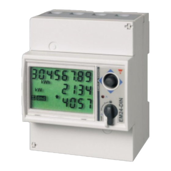
1. Introduction and usage
This document is the manual for the EM24 three phase max 65 A per phase Energy Meter. As shown
in the picture above.
Note that this product is no longer sold. Use the
https://www.victronenergy.com/accessories/wired-ac-sensor
The Energy Meter can be used for four things:
1.
Grid meter, and used as control input for an
2.
Measure the output of a PV Inverter
3.
Measure the output of a AC Genset
4.
(deprecated) Grid meter, used as control input for a
(1) In case the meter is used as a grid meter in a single phase installation, it is possible to use the
second phase to measure the output of a PV Inverter. Note that this does not work properly, use the
ET340 instead. See
Energy Meters FAQ, Q5
The meter is connected to the Color Control GX. There are two options in its wiring:
1.
Direct connection, either using the RS485 to USB interface with 1.8m cable length, or the 5.0m
cable.
2.
Wireless connection via Zigbee
The REL200100000 is the EM24DINAV93XISX from Carlo Gavazzi. Other EM24 models from Carlo
Gavazzi can also be used, as the communication is the same. For example the EM24DINAV53DISX,
which uses Current Transformers and can therefore work in systems > 63A per phase, has been
tested and works. Note that this model is not stocked by Victron Energy, we recommend to purchase
Victron Energy - https://www.victronenergy.com/live/
1/7
ET340
for new installations.
ESS System
(1).
Hub-4 system
for details.
Energy Meter EM24 manual
Advertisement
Table of Contents

Subscribe to Our Youtube Channel
Related Manuals for Victron energy EM24


Summary of Contents for Victron energy EM24
- Page 1 Energy Meter EM24 manual 1. Introduction and usage This document is the manual for the EM24 three phase max 65 A per phase Energy Meter. As shown in the picture above. Note that this product is no longer sold. Use the ET340 for new installations.
-
Page 2: Phase Diagram
Last update: 2017-07-19 14:55 energy-meters:em24 https://www.victronenergy.com/live/energy-meters:em24 it locally. 2. AC Wiring and front selector 3-phase diagram: When used to measure a PV Inverter, terminals 1, 4 and 7 should face the PV inverter to ensure correct direction of current and power. - Page 3 2017-08-15 16:55 Energy Meter EM24 manual On the CCGX go to the grid meter in the Wired AC sensor settings. Make sure 'Phase type' is set to 'Single phase' and 'PV inverter on phase 2' is enabled. Front selector Change the front selector so it is not in the locked state. This will allow it to be automatically configured by the rest of the system the meter.
- Page 4 Last update: 2017-07-19 14:55 energy-meters:em24 https://www.victronenergy.com/live/energy-meters:em24 power from the CCGX, so the CCGX needs to be switched on as well). Step 2. Connect the Zigbee to RS485 converter to the EM24 energy meter: Zigbee Converter Energy meter Terminal 43 Terminal 42 Terminal 41 Step 3.
- Page 5 2017-08-15 16:55 Energy Meter EM24 manual Connect the 12V DC power supply to the Zigbee to RS485 converter. When the power is switched on, check the LEDs again. Option B: Wired connection to CCGX Connect the Energy Meter to the CCGX with an USB to RS485 cable (see our price list). The RS485 to USB interface cable between the CCGX and the Energy Meter can be extended up to 100 meters;...
- Page 6 Last update: 2017-07-19 14:55 energy-meters:em24 https://www.victronenergy.com/live/energy-meters:em24 The menu lists every meter found. And in the gray box at the right side it shows the configured function. After selecting a meter, see its detailed settings: 5. Multiple Energy Meters in one system There are 3 options to connect multiple Energy Meters: Each wired to a separate RS485-USB converter.
- Page 7 2017-08-15 16:55 Energy Meter EM24 manual second phase to measure the output of the PV Inverter. See see the AC Wiring chapter in this manual. 6. Changing the modbus address Press the joystick down until until the display shows 'Pass'. The joystick on the right side on the display, above the front selector).
Need help?
Do you have a question about the EM24 and is the answer not in the manual?
Questions and answers