
Related Manuals for Victron energy VM-3P75CT


Summary of Contents for Victron energy VM-3P75CT
- Page 1 ENGLISH Victron VM-3P75CT Energy Meter Manual Rev 00 - 11/2023 This manual is also available in HTML5.
-
Page 2: Table Of Contents
Victron VM-3P75CT Energy Meter Manual Table of Contents 1. Safety Instructions ........................1 2. Introduction ........................... 2 2.1. Features ........................2 2.2. What's in the box? ......................3 3. Installation ..........................4 3.1. AC wiring ........................4 3.2. AC wiring diagrams ......................5 3.3. -
Page 3: Safety Instructions
1. Safety Instructions General Please read the safety instructions below before installing and using the VM-3P75CT energy meter to avoid risks of fire, electric shocks, personal injuries or equipment damage. This product is designed and tested in accordance with international standards. The equipment should be used for its designated application only and in accordance with the specified operating parameters. -
Page 4: Introduction
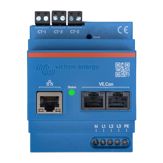
2. Introduction The Victron VM-3P75CT energy meter is a standard device to measure the power and energy of single- and three-phase applications, for example, at the distribution box or to measure the output of a PV Inverter, AC Genset or the output of an inverter and inverter/charger. -
Page 5: What's In The Box
Victron VM-3P75CT Energy Meter Manual 2.2. What's in the box? Victron VM-3P75CT with 3 input terminal blocks 3x Split-core current transformer, wired ready for connection Wire length: 640mm (25.3in) VE.Can terminators (2 pcs) Page 3 Introduction... -
Page 6: Installation
Victron VM-3P75CT Energy Meter Manual 3. Installation 3.1. AC wiring Note the following when installing: • It is not allowed to use the current clamps on bare wires. • As the current transformers are quite delicate, the following procedure should be followed when installing the current transformers: First, open Section A. -
Page 7: Ac Wiring Diagrams
VM-3P75CT 3 Phase Wiring - Role is set to measure AC loads Switch or circuit breaker Fuse 500mA 3P PV Inverter or Genset VM-3P75CT VM-3P75CT 3 Phase Wiring - Role is set to measure a PV Inverter (or Generator) Page 5 Installation... -
Page 8: Ethernet And Ve.can Wiring
3.3. Ethernet and VE.Can wiring The VM-3P75CT can be connected to the GX device either via VE.Can or Ethernet. Suppose there is a local network with an Ethernet connection (via a router) to which the GX device is connected via Ethernet or WiFi. -
Page 9: Configuration & Monitoring
Portal) The VM-3P75CT supports Instant Readout of key data (total power and power per phase) at a glance directly from the Device list (1) in VictronConnect. This works via a local network connection and VictronConnect-Remote (VC-R). The data display in VictronConnect is divided into a Status page (2) for status messages of the individual phases and an Energy page (3) with the overview of the fed-in and purchased energy per phase. - Page 10 Once the Role has been properly set, the configuration is done. GX device monitoring After the VM-3P75CT has established a connection to the GX device in the local network, the device must be activated in the Modbus TCP/UDP menu so that it appears in the Device List.
- Page 11 Victron VM-3P75CT Energy Meter Manual Page 9 Configuration & Monitoring...
-
Page 12: Led Codes
Victron VM-3P75CT Energy Meter Manual 4.1. LED codes The VM-3P75CT has a built-in LED that shows the status of the energy meter. The LED states are as follows: • Blinking fast alternately green/red: Bootloader/update mode. • Solid green: All ok, normal running mode. -
Page 13: Firmware Updates
Victron VM-3P75CT Energy Meter Manual 5. Firmware Updates The firmware of the VM-3P75CT can be updated in multiple ways: • VRM: Remote firmware update: This works over Ethernet and VE.Can connection • VictronConnect-Remote (VC-R): This works over Ethernet and VE.Can connection •... -
Page 14: Restart And Reset To Factory Defaults
6. Restart and reset to factory defaults The VM-3P75CT has a recessed RESET button that allows you to reset the energy meter to factory defaults or to restart the device if a problem occurs without interrupting the power supply. In addition, a factory reset can also be carried out via VictronConnect. -
Page 15: Troubleshooting
Performing a firmware update via VictronConnect Remote (VC-R) in bootloader mode is impossible. 7.2. Error codes The VM-3P75CT indicates an error by turning the LED solid red when an error is present. Simultaneously, an error code appears on the GX device, VRM, and VictronConnect. -
Page 16: Technical Data
Victron VM-3P75CT Energy Meter Manual 8. Technical data 8.1. Technical specifications VM-3P75CT REL200300100 VOLTAGE INPUTS Voltage connection Direct Input voltage range L-N 85 to 265VAC Input voltage range L-L 150 to 460VAC Frequency 50/60Hz CURRENT INPUTS Current connection Via current transformers (included - wire length 640mm (25.2in) -
Page 17: Enclosure Dimensions
Victron VM-3P75CT Energy Meter Manual 8.2. Enclosure dimensions Dimension Drawing - VE-EnergyMeter REL200300100 Energy Meter VM-3P75CT 71.2 58.9 Dimensions in mm Page 15 Technical data...
Need help?
Do you have a question about the VM-3P75CT and is the answer not in the manual?
Questions and answers