TECSYSTEM t154 Instruction Manual
Hide thumbs
Also See for t154:
- Manual (23 pages) ,
- Instruction manual (20 pages) ,
- Instruction manual (13 pages)
Table of Contents

Related Manuals for TECSYSTEM t154


Summary of Contents for TECSYSTEM t154
- Page 1 INSTRUCTION MANUAL T154 1MN0101 REV. 0 operates with ISO9001 certified quality system TECSYSTEM S.r.l. 20094 Corsico (MI) Tel.: +39-024581861 Fax: +39-0248600783 http://www.tecsystem.it R. 1.6 06/09/17 ENGLISH “Translations of the original instructions”...
-
Page 2: Table Of Contents
INTRODUCTION First of all we wish to thank you for choosing to use a TECSYSTEM product and recommend you read this instruction manual carefully: You will understand the use of the equipment and therefore be able to take advantage of all its functions. -
Page 3: Safety Requirements
POWER SUPPLY The series T154 ED16 has UNIVERSAL power supply, i.e. it can be supplied by 24 to 240 Vac-Vdc, irrespectively of polarity in Vdc.Before using it, make sure the power cable is not damaged, knotted or pinched. Do not tamper with the power cable. -
Page 4: Accessories
1 Pt100 sensor terminal 12 poles pitch 3.81 Code: 2PL0420- Screws tightening torque 0,25Nm 1MN0030 REV. 2 ATTENTION: always install the device using the terminals included in the pack. The use of terminals other than those included with the control unit might cause malfunctions. T154... -
Page 5: Technical Specifications
T154 TECHNICAL SPECIFICATIONS POWER SUPPLY Supply rated values 24-240 Vac-Vdc 50/60Hz Maximum and minimum supply values 20-270 Vac-Vdc 50/60Hz ● Vdc with reversible polarities INPUTS ● 4 inputs for RTD sensors, Pt100 type with 3 wires (max section 1.5mm²) ●... - Page 6 T154 TECHNICAL SPECIFICATIONS TESTS AND PERFORMANCE ● Frontal film polycarbonate IP65 ● Housing NORYL 94 _V0 Absorption 7,5VA ● ● Data memory 10 years minimum ● Digital linearity of sensor signal ● Self-diagnostic circuit Protection treatment of the electronic part...
-
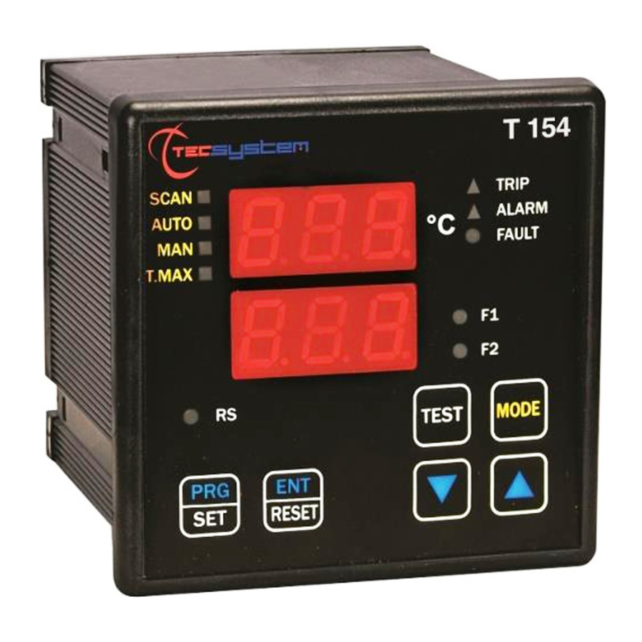
Page 7: Front Panel
T-max mode selection (red) LED FAN 2 (yellow) LED (not used) Man mode selection (yellow) LED Display mode selection button Auto mode selection (green) LED Fixing block Scan mode selection (yellow) LED 10) UP key Fixing block 11) DOWN key T154... -
Page 8: Display
The second display to the visualisation of the monitored channel. When the device is switched on or following a reset, the display shows: the control unit model, T154 (BAS no options, C01 T154-V-) with VER "00" (firmware version) and temperature range of the unit. -
Page 9: Mounting
Drill a 92 x 92 mm hole in the panel sheet. 1MN0007 REV. 0 Control unit Panel hole dimensions (+0.8mm tolerance) Identification label Fix the unit securely with the blocks supplied. 1MN0008 REV.0 Control unit Fixing screw Fixing block Crosshead screwdriver #1X100mm T154... -
Page 10: Electrical Connections
ELECTRICAL CONNECTIONS T154 1MN0125 REV. 0 Pt100 sensors (white-red-red) Relays (FAN1-ALARM-TRIP-FAULT) Supply 24-240Vac-dc 50/60Hz. Note: relay contact image in non-alarm condition, with the exception of the FAULT relay that switches: contact 11-12 open (NO), contacts 11-12 closed (NC) fault condition identification. Read the Alarms and Ventilation paragraph on page 11 and see the fault contact switching. -
Page 11: Power Supply
To protect the monitoring device from line overvoltages, we suggest you use the PT-73- 220 electronic discharger, designed by TECSYSTEM S.r.l. for this specific purpose. As an alternative we suggest using 110 Vac or, even better, 110 Vdc supply voltages. -
Page 12: Programming
PROGRAMMING T154 STEP PRESS EFFECT PRESS NOTES Keep the PRG key pressed until the display shows PRG SET Select PRG SET for entering in the programming mode or PRG 1 default value PRG 1 to restore the default programmed value. - Page 13 (°C/sec) Set the desired value Default "no" (function (FCD page 16) excluded) for version T154 (BAS) jump to the step 26 VOT (YES) is displayed C01 T154 -V- (See VOTING on page 19) Default YES solo per Set YES or NO...
-
Page 14: Temperature Sensors
/ electrical fault of the Pt100 sensors damage to the Pt100 inputs of the control unit. TECSYSTEM S.r.l. has designed its own special cable to transfer the measurement signals, CEI-compliant, with all the protection requirements provided for: model CT-ES 1MN0035 REV. -
Page 15: Temperature Sensor Diagnostics
(programmed parameter display) and modified in PRG (programming) mode. COOLING FAN CONTROL The T154 control unit is fitted with one FAN contacts (FAN1), if programmed correctly, can control the fans switching ON and OFF to cool the transformer. The FAN1 contact can manage cooling the transformer or the room where it is installed. -
Page 16: Technical Specifications Of The Extension Cable For Pt100
In this specific case we recommend the FCD function to be set in a temperature range of between 20°C and 30°C. This setting is recommended in order to prevent the FCD function from activating during motor startup, or where the ΔT/sec. increase varies quickly. (*) The ΔT value shows the temperature range for each second T154... -
Page 17: Warranty Conditions
Returning used electrical devices: contact TECSYSTEM or your TECSYSTEM agent for information on the correct disposal of the devices. TECSYSTEM is aware of the impact its products have on the environment and asks its customers active support in the correct and environmentally-friendly disposal of its devices. -
Page 18: Failsafe Function
FAILSAFE FUNCTION The T154 has n.o selection (contact open ) / n.c (normally closed contact) for ALARM, TRIP and FAULT relays, programming steps 26 to 31 page 13. The selection of the setting YES/NO introduces functions Fail Safe and No Fail Safe. -
Page 19: C01 T154 -V- Ed16 Changes Version
C01 T154 -V- ED16 CHANGES VERSION When at the starting the device shows the message T154 C01 means that: you have purchased the model T 154 -V- What are the changes introduced in the T154 model -V-: Programming with default values: ALARM 120 ° C (CH1-2-3) - TRIP 135 ° C (CH1-2-3) - FAN YES (CH1-CH2-CH3) - FAN ON 90 °...
Need help?
Do you have a question about the t154 and is the answer not in the manual?
Questions and answers