Table of Contents
Advertisement
Quick Links
Advertisement
Table of Contents

Related Manuals for TECSYSTEM NT539


Summary of Contents for TECSYSTEM NT539
- Page 1 INSTRUCTION MANUAL NT539 1MN0143 REV.0 operates with ISO9001 certified quality system TECSYSTEM S.r.l. 20094 Corsico (MI) Tel.: +39-024581861 Fax: +39-0248600783 http://www.tecsystem.it R. 1.2 26/11/20 ENGLISH “Translations of the original instructions”...
-
Page 2: Table Of Contents
INTRODUCTION First of all we wish to thank you for choosing to use a TECSYSTEM product and recommend you read this instruction manual carefully: You will understand the use of the equipment and therefore be able to take advantage of all its functions. -
Page 3: Safety Requirements
POWER SUPPLY The NT539 has UNIVERSAL power supply, i.e. it can be supplied by 24 to 240 Vac-Vdc, irrespectively of polarity in Vdc. Before using it, make sure the power cable is not damaged, knotted or pinched. Do not tamper with the power cable. Never disconnect the unit by pulling the cable, avoid touching the pins. -
Page 4: Accessories
3 Pt100 sensor terminals 12 poles pitch 3.5 Code: 2PL0375- Screws tightening torque 0,25Nm 1MN0030 REV. 2 ATTENTION: always install the device using the terminals included in the pack. The use of terminals other than those included with the control unit might cause malfunctions NT539... -
Page 5: Technical Specifications
NT539 TECHNICAL SPECIFICATIONS POWER SUPPLY Supply rated values 24-240 Vca-Vdc 50/60Hz ● Vdc with reversible polarities INPUTS ● 9 inputs for RTD sensors, Pt100 type with 3 wires (max section 1.5mm²) subdivided in 3 groups (1-9, 10-18,19-27) ● Connections on removable terminal strips ●... - Page 6 NT539 TECHNICAL SPECIFICATIONS TESTS AND PERFORMANCE ● Housing PPO UL 94 _V0 Absorption 6VA ● ● Digital linearity of sensor signal ● Self-diagnostic circuit Protection treatment of the electronic part Option DISPLAY AND DATA MANAGEMENT ● 2x13mm displays with 3 digits to display temperatures, messages and channels 4 LED’s to show the display mode (SCAN, AUTO, MAN, TMAX)
-
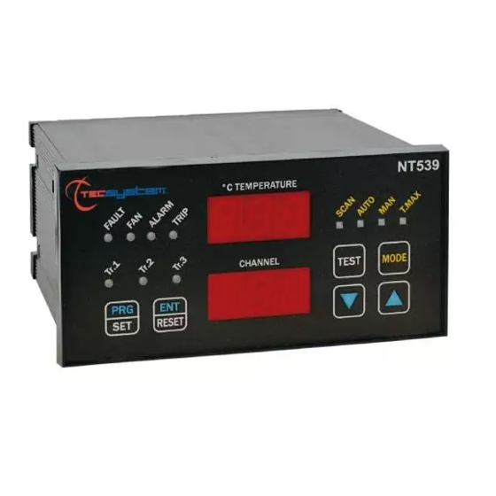
Page 7: Front Panel
Scan mode selection (yellow) LED TR.3 (red) LED Auto mode selection (green) LED Enter/Reset button Man mode selection (yellow) LED TR.2 (red) LED T-max mode selection (red) LED Programming / Setting button 10) Control unit series TR.1 (red) LED NT539... -
Page 8: Display
We suggest carrying out the control unit LED test regularly. For this operation, press the TEST key briefly; all the displays turn on for 2 seconds. If one of the LEDS does not work, please return the control unit to TECSYSTEM for repair. ALARM RELAY TEST This function allows carrying out a test of the relay operation without having to use any other devices. -
Page 9: Mounting
Drill a 139 x 67 mm hole in the panel sheet. 1MN0142 REV. 0 Panel hole dimensions (+0.8mm tolerance) Control unit Identification label Fix the unit securely with the blocks supplied. 1MN0144 REV.0 Control unit Fixing screw Fixing block Crosshead screwdriver #1X100mm NT539... -
Page 10: Electrical Connections
ELECTRICAL CONNECTIONS NT539 1MN0145 REV. 0 Pt100 sensors (white-red-red) Relays (TR1-TR2-TR3) Supply 24-240Vac-dc 50/60Hz. Note: relay contact image in non-alarm condition, with the exception of the FAULT relay that switches: contact 63-64 open (NO), contacts 63-64 closed (NC) fault condition identification. Read the Alarms and Ventilation paragraph on page 11 and see the fault contact switching. -
Page 11: Power Supply
POWER SUPPLY The NT539 has UNIVERSAL power supply, i.e. it can be supplied by 24 to 240 Vac-Vdc, 50/60Hz irrespectively of polarity in Vdc (terminals 40-42). This is obtained thanks to the use of a tested power supply unit, newly designed and manufactured, that frees installers from worrying about the correct Vac and Vdc supply. -
Page 12: Programming
PROGRAMMING NT539 STEP PRESS EFFECT PRESS NOTES Keep PRG key pressed until PRG led turns on. After PRG indication, the transformer (or coils) number that you want to check appears. On “channel” display appears NTR Default 3 Set the desired number (1-2-3) - Page 13 ATTENTION: We recommend you check the unit's programming before starting the device. The default parameters set by TECSYSTEM might not match your requirements. Programming the device is the end user's responsibility, the settings of the alarm thresholds and the enabling of the functions described in this manual must be checked (by a specialized engineer) according to the application and features of the system where the control unit is installed on.
-
Page 14: Temperature Sensors
/ electrical fault of the Pt100 sensors c) damage to the Pt100 inputs of the control unit. TECSYSTEM S.r.l. has designed its own special cable to transfer the measurement signals, CEI-compliant, with all the protection requirements provided for: model CT-ES 1MN0035 REV. -
Page 15: Temperature Sensor Diagnostics
(programmed parameter display) and modified in PRG (programming) mode. COOLING FAN CONTROL The NT539 control unit is fitted with one FAN contacts, if programmed correctly, can control the fans switching ON and OFF to cool the transformer (TR1-TR2-TR3). The FAN contact can manage cooling the transformer. The FAN led ON on the channel displayed indicates the exceeding of the threshold. -
Page 16: Technical Specifications Of The Extension Cable For Pt100
(*) The ΔT value shows the temperature range for each second IMPORTANT WARNING Before carrying out the isolation test of the electrical panel the control unit is installed on, disconnect it together with the sensors from the power supply, to prevent it from being seriously damaged. NT539... -
Page 17: Warranty Conditions
Returning used electrical devices: contact TECSYSTEM or your TECSYSTEM agent for information on the correct disposal of the devices. TECSYSTEM is aware of the impact its products have on the environment and asks its customers active support in the correct and environmentally-friendly disposal of its devic... -
Page 18: Useful Contacts
USEFUL CONTACTS TECHNICAL INFORMATION: ufficiotecnico@tecsystem.it COMMERCIAL INFORMATION: info@tecsystem.it NT539...
Need help?
Do you have a question about the NT539 and is the answer not in the manual?
Questions and answers