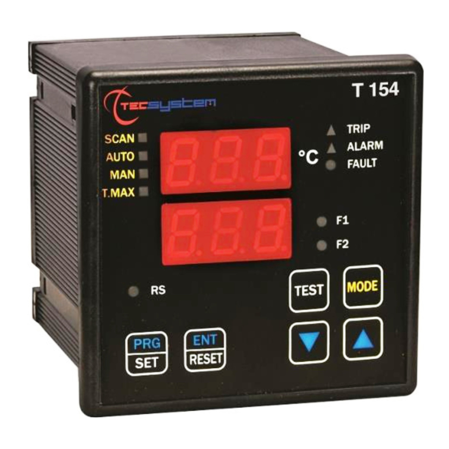
TECSYSTEM T154 Instruction Manual
P4 v3 1.2c
Hide thumbs
Also See for T154:
- Manual (23 pages) ,
- Instruction manual (20 pages) ,
- Instruction manual (19 pages)
Summary of Contents for TECSYSTEM T154
- Page 1 INSTRUCTION MANUAL TECSYSTEMS S r. I. T154 P4 V3 1.2C Exclusive Canadian Distributor EL Switchgear & Control Inc Ph: 1 800 463 1275 Fax 1 519 753 5755 E Mail elsc@on.aibn.com February 19, 2007...
-
Page 2: Table Of Contents
Technical Specifications ...............11 Testing ....................12 Warranty ....................12 Troubleshooting ..................13 Options....................14 Approvals....................14 T154 Instruction Manual P4 V3 1.2C February 19, 2007 Exclusive Canadian Distributor EL Switchgear & Control Inc Ph: 1 800 463 1275 Fax 1 519 753 5755 E Mail elsc@on.aibn.com... -
Page 3: Introduction
Introduction The T154 Temperature Monitor will monitor and control up to four, three- wire RTD inputs. All input channels may be user programmed for two separate outputs with a range of 0 to 240°C (32 to 464°F). The set points are common to all channels. -
Page 4: Controls
Controls All functional controls and displays are located on the front of the unit. The unit has six input keys, two having dual functions. These are PRG/SET and ENT/RESET. Keys may be categorized as, programming, screen display, and test. Programming keys are located at the bottom of the unit and may be identified by the blue type. -
Page 5: Screen Messages
If any lamp is not functioning the unit must be returned for repair. Control Power The T154 has a universal power supply. It can be supplied with 24 to 240V AC or DC without respect to polarities. The ground cable must be fixed to terminal # 41... -
Page 6: Wiring
Failure to do so may result in damage to the unit. Wiring Terminal blocks are located at the rear of the unit for all input channels (4), output relays (4) and control power. The terminal blocks are removable for ease of wiring Wiring connections are shown in Figure 2 Figure 2 Wiring (Cont.) -
Page 7: Inputs
The T154 will accept three or four, three-wire RTD inputs. The standard unit is calibrated for 100-ohm, platinum RTDs. The T154 may also be ordered for use with 100 or120-ohm, nickel RTDs. Channels 1-2-3 must have inputs connected or the unit will read an open circuit with the FOC message displayed, and the fault relay tripped. -
Page 8: Programming
Programming Getting started Programming the T154 is simple and requires no special tools. The set point values for alarm, trip and fan control should be at hand. The unit will automatically step through each program sequence and upon completion will repeat each step or may be returned to normal operation. - Page 9 Enter Program Values 1) Input set point temperature value for alarm Screen display: numerical value, yellow alarm LED flashing, green chn indicators 1-2-3 Action: Scroll up/down, using up down keys Options: 0-240°C (32-464°F) Complete: Press PRG—Advance Discontinue: Press ENT 2) Input set point temperature value for trip Screen display: numerical value, red trip LED flashing green chn indicators 1-2-3 Action: Scroll up/down using up-down keys...
-
Page 10: Pictorial
Pictorial Exclusive Canadian Distributor EL Switchgear & Control Inc Ph: 1 800 463 1275 Fax 1 519 753 5755 E Mail elsc@on.aibn.com February 19, 2007... -
Page 11: Technical Specifications
TECSYSTEM S.r.i ™ TECHNICAL SPECIFICATIONS Auxiliary Power Supply Communication • • Rated voltage 24-240 Vac-dc Not available • Maximum ratings 20.270 Vac-dc • Vdc with reversible polarities Outputs Inputs • Three alarm relays (Alarm -Trip-Fan) • • One-alarm relay for sensor fault or working Four inputs RTD PT 100 sensors –... -
Page 12: Testing
Warranty The T154 is warranted for a period of 12 months from date of shipment. Warranty is limited to repair or replacement of the defective product and no contingent liabilities will be accepted. -
Page 13: Troubleshooting
Troubleshooting Problem Causes / Solution The unit will not switch on, with control power Check the terminal block for correct installation energized Check for voltage at terminal block The sensor is damaged The fault relay closes and the fault switches on. The red LED of the respective channel is illuminated. -
Page 14: Options
• Protective display cover Options • 120 or 100 ohm nickel RTD input • Assembled in accordance with CE rules. Approvals • Protection against electrical and magnetic noises CEI -EN50081-2/50082-2 • C-UL approval, File No, 190427 Exclusive Canadian Distributor EL Switchgear & Control Inc Ph: 1 800 463 1275 Fax 1 519 753 5755 E Mail elsc@on.aibn.com...


Need help?
Do you have a question about the T154 and is the answer not in the manual?
Questions and answers