Table of Contents
Advertisement
Advertisement
Table of Contents

Related Manuals for TECSYSTEM NT579


Summary of Contents for TECSYSTEM NT579
- Page 1 TECSYSTEM SHANGHAI INSTRUCTION MANUAL NT579 STANDARD & DIGITAL (24 Vdc) TECSYSTEM SHANGHAI 3rd Floor, Block No.5, For- ward High-tech Industrial Park, No.33, Fuhua Road, Jiading District SHANGHAI - CHINA http://www.tecsystem.asia R.1.4 2015/08/10 NT579-NT579 RS485...
- Page 2 TECSYSTEM SHANGHAI INTRODUCTION NT579 is a microprocessor electronic device designed to integrate the ther- mal control of resin-cast transformers . The monitoring unit has separated and independent inputs and outputs: 3 3-wire Pt100 inputs for each winding (total 3 inputs)
- Page 3 13.2Hz Acceleration ± 0.7G from 13.2Hz to 100Hz. (*) Seismic test according to IEEE 344-1.987 *Cross reference T154 for construc- tive analogy. DIMENSIONS 162 x 82 mm depth 130 mm (terminal boxes included) Panel cut-out 152x76 mm NT579-NT579 RS485...
- Page 4 Firmly tighten the device with the enclosed fixing kit. 3) SUPPLY OF NT579 CONTROL DEVICE NT579 has a power supply of 18~36Vdc 50-60 Hz When the monitoring device is directly fed from secondary winding of the transformer to be protected, it can be damaged by high-intensity overvolt- ages.
-
Page 5: Temperature Sensor Connection
Figure 2 Page 11 shows the position inside the terminal box of the connection ca- TECSYSTEM has designed an own special cable to transfer the measuring signals, according to CEI standards, with all the protection requirements pro- vided for : model CT-ES bles to the monitoring device. -
Page 6: Cooling Fan Control
ALARM and TRIP relay switching, they de-energise with consequent turning off of the relevant LED’s. 11) COOLING FAN CONTROL NT579 monitoring unit, if opportunely programmed, can control ON-OFF of fans accompanying the transformer, according to set temperatures. 12) FAN TEST It is possible, through programming (HFn), impose that fans are activated for 5 minutes each “xxx”... -
Page 7: Display Mode
Alarm 90 ° C, 119 ° C Trip, yes Fan, Fan on 70 ° C, 60 ° c Fan off, Fcd no, no HFN, Adr 1, Par eve , Bdr 19.2, 4.20 Out scan. Reprogram the desired values and ensure that these are stored. In case of error Ech permanent return the equipment to Tecsystem SH for repair.. CAL ERROR. -
Page 8: Important Notice
Fan-on thresholds must be higher than the Fan-off thresholds. In case you try to load these thresholds in a wrong way, NT579 monitoring unit won’t proceed with the programming and data storage; therefore in the coming readings you will read the data relevant to the previous pro- gramming's. - Page 9 Channel logs can be read with code 3 from number 1 to number 18 WORKING NOTES The modbus inside option allow to connect NT579 monitorning unit with a RS485 network With MODBUS RTU protocol in order to read the data shown in the table at pag.
- Page 10 Fan cyclic test for 5 min- 12 PRG/SET display shows HFN utes each “n” hours Load desired number of hours no= disabled function Fault for temperature 14 PRG/SET FCD threshold appears fast increase (° C/sec) NT579-NT579 RS485...
- Page 11 8. The serial communication of the temperature control monitoring unit is ac- tive just when NT579 is in temperature control working mode in one of the intended modes (Scan, Auto, Man and T.Max). When other functions such as programming, programming display and re- lay test are activated, the ModBus communication is temporarily deacti- vated.
-
Page 12: Rs485 Electrical Connections
TECSYSTEM SHANGHAI DATA TRANSMISSION ON MODBUS NETWORK The MODBUS INSIDE option allows to connect NT579 monitoring unit with a RS485 network with Modbus RTU protocol in order to read and write the data shown in the table MODBUS MAPPING at pag.13. The unit is always in slave mode. -
Page 13: Data Packet
ERROR CODES (exception code) In case of wrong request ModBus will answer with modified codes and codified errors according to the following points: - Non-supported function code - Wrong data address - Wrong data (for instance length) -illegal data(for value) NT579-NT579 RS485... -
Page 14: Crc Calculation
, Starting address HI, Starting address LO, Num- (10) ber of Point HI, Number of Point LO, Byte count, Data HI, Data LO……., Crc LO, Crc HI. The alarm thresholds (registers 3-4-5-6) are written only for channel L1 NT579-NT579 RS485... - Page 15 2’compl. Ch L1 tem- 2’compl. from 1° perature sign to 220 Fan off set point 2’compl. from – 2’compl. Ch L2 tem- 20° to sign perature 2’compl. 2’compl. Ch L2 from 1° sign Maximum to 220 temperature NT579-NT579 RS485...
-
Page 16: Modbus Mapping
2’compl. Ch L3 tem- perature 2’compl. sign from 1° to 220 alarm set point 2’compl. Ch L3 tem- perature from 1° to 220 2’compl. sign trip set point 2’compl. Ch L3 temperature from 1° to 2’compl. sign Fan on set point NT579-NT579 RS485... - Page 17 See CHn story note channel L2 Ch L2 story Alarm history See CHn story note channel L3 Ch L3 story Alarm history setting fan test 0=No test cycle (hours) 1~200h detector tem- 0=No FCD perature incre- ment fast 1~30° /sec NT579-NT579 RS485...
- Page 18 Not used TRIP ALARM Not used CH L1-L2-L3 STORY CH A-b-c STORY BIT 7 BIT 6 BIT 5 BIT 4 BIT 3 BIT 2 BIT 1 BIT 0 Not used TRIP ALARM Not used Not used Not used NT579-NT579 RS485...
-
Page 19: Causes And Remedies
A strong disturbance damaged the stored dataplease refer paragraph 8. When turning on, “ECH” indication ap- If this problem should persist, please pears contact TECSYSTEM SH Technical De- partment. Wrong sensor connections. Terminal box connected inside out. All the Pt100 sensor are in FCC. - Page 20 When a channel is in Fault condition for FCD, relevant Alarm and trip signalling are inhibited in order to just report the anomaly for too fast increase of the temperature. Press Reset to cancel the FCD signalling of all the channels and restore the fault relay. NT579-NT579 RS485...
-
Page 21: Rs485 Digital Output
RELAYS CONNECTION RELAYS NOTE: when the unit is powered the fault relay 54-55 opens and it closes again in case of fault condition or no power. Relay fan contact ON/OFF 50 51 52 53 54 55 56 57 TRIP ALARM FAULT POWER SUPPLY 18~36 Vdc BE CAREFUL TO CONNECT THE POWER SUPPLY WITH THE RIGHT POLARITY RS485 DIGITAL OUTPUT REAR PANEL NT579-NT579 RS485... - Page 22 The Product purchased is covered by manufacturer's warranty or the seller's terms and conditions set forth in the "General Conditions of Sale Tecsystem SHANGHAI", available at www.tecsystem.asia and / or purchase agreement. The warranty is considered valid only when the product will be damaged by causes attributable to TECSYSTEM SHANGHAI, such as manufacturing or components defects.
- Page 23 TECSYSTEM SHANGHAI NT579-NT579 RS485...
- Page 24 TECSYSTEM SHANGHAI NT579-NT579 RS485...
- Page 25 TECSYSTEM SHANGHAI 使用手册 系列 NT579 STANDARD & DIGITAL (24 Vdc) 中国上海市嘉定区复华路33号5幢B区三层 邮编:201818 电话: +862139905855/56/57-118 传真: +862139905859 http://www.tecsystem.asia R.1.2 2015/08/10 NT579-NT579 RS485 智能温控器...
- Page 26 ·RS485 MODBUS RTU 输出 • 2 级报警输出(高温报警-跳闸) • 1 路故障FAULT输出 • 每个报警继电输出触点容量:5A-250Vac • 1路风机启、停无源控制输出,容量为12A, 250Vac (cos Φ=1) • 1路RS485数字输出(NT579dig) 测试以及性能 • 按照CE规范的要求进行组装 •抗电噪声干扰符合CEI-EN-61000-4-4 •温控器绝缘强度不低于2.5kVac:变送器和电源之间,变送器和传感器之 间和电源和传感线之间的绝缘强度均为2.5kVac,历时1分钟 •精度为± 1%,分辨率± 1° C •操作温度为:-20 ° C 至 +60° C • 非露点湿度为90% • 前面板为聚碳酸酯材料,IP54防护等级 NT579-NT579 RS485 智能温控器...
- Page 27 • 4个LED用于显示当前温控器的显示模式 (自动循环,最高温度,手动设置和黑盒子四种显示模式) •4个LED显示对应的输出报警状态(高温,跳闸,故障和风机启动) •1个LED用于RS485通讯工作显示(NT579dig) • 温度监控范围0° C 至200° C • 可对通道CHL1-L2-L3进行(高温报警ALARM和跳闸TRIP)两级报警 设定 •可自行设定风机启动/停止的温度门槛值 • 传感器自检功能: Fcc 报警:传感器短路 Foc 报警:传感器开路 数据存储诊断(Ech) • • 通过面板按键方便的进行编程操作 •编程错误自动显示(Err) • 带有清除报警操作面板按键 尺寸 • 162 x 82 mm-高度130mm(包括接线端子) • 嵌装开口尺寸:152 x 76 mm NT579-NT579 RS485智能温控器...
- Page 28 TECSYSTEM SHANGHAI 2)安装 嵌装开口尺寸为152× 76mm 用附带的紧固件进行仪表锁紧。 3) 电源供应 NT579仪表特点为内置有高频开关通用电源模块,可适用电压范 围:18~36Vdc 注意:当温控器从变压器二次回路直接供电时,可能会被变压器的 电压瞬变所损坏, 特别是变压器空载的时候,尤其容易发生此类故障。 如果用户由于某种原因,需要更换温控器,用户必须将所有的接线端子 连同温控器一起更换为新的。以防止,原来的接线端子不匹配造成连 接不良。 有关风机控制与报警输出端子的连接 4) 首先将可拆卸接线端子从设备上拆下,然后在其上进行接线操作。 只有当达到设置的温度门槛值时,报警和跳闸输出触点才会发生触发。 FAULT 继电触点只在仪表出现故障的情况下触发,例如PT100传感器故 障,数据内存故障,供电电压缺陷,仪表校验故障。 当仪表处于编程状态、编程查看模式或继电器测试状态时,所有的输出 继电器均处于关闭状态(仪表无电状态) FAN控制触点可用于变压器冷却风机的启停控制,无源,仅开关量。 请断开电源后,进行所有连接,FAULT故障报警继电输出,是针对温度 监控系统本身的故障或环境干扰造成的报警,一定注意不能连接到 变压器的跳闸控制线路上。 建议在风机和温控器的连接线路上,根据实际的负载,加装一个电容保 护。 NT579-NT579 RS485 智能温控器...
- Page 29 第23页的图2显示了具体的接线位置。 6)测量信号传输 所有测量所用的Pt100的传输电缆都必须严格符合如下要求: • 与电源供应线分隔 • 导线必须为屏蔽和互绞设计 • 至少具有0.12 mm² 的横截面 • 如不带屏蔽也必须要互绞设计 • 导线和接线端子排必须要紧固连接 • 导线末端必须加焊锡或套上镀银端子 所有的“NT”系列温控器均采用线性函数信号计量方法,整个检测范围 内 TECSYSTEM S.r.l.公司按照CEI标准的规定设计了一种专用信号传输电 缆,可以防止各种干扰。其型号为:CT-ES 温度传感器诊断 7) 一旦安装在被保护设备上的温度传感器发生损坏,故障(FAULT)继电 器则会立即闭合,并且在显示屏上显示相关故障通道。 • Fcc为传感器短路或者检测到温度低于-15° C • Foc为传感器开路 • Fcd 异常温升报警功能(请看第22页的注解) 如果要清除错误信息和故障(FAULT)报警状态进行重新设置之前,用 户必须确保故障传感器已经修复或者更换。如果发生FCD,FCC或Foc 报警,用户无需过分紧张这个不会造成对变压器的误动作。 NT579-NT579 RS485 智能温控器...
- Page 30 通道 ChL1-L2-L3= 90° C, TRIP跳闸 通道 ChL1-L2-L3=119° C, Ch-Fan=L1-L2-L3,Fan—on(冷却风机开启)=70° C,Fan-off(冷却风 机关闭)=60° C, HFn(风机自检时间)=000,FCD=no, Adr=1,Par=eve, Bdr=19.2, 4.20输 出为SCAN模式。 通过按下RESET键来消除Ech报警显示,并且运行编程以输入所需值。 设定好之后,按下TEST键进行程序测试;如果Ech报警仍然出现,则说 明仪表硬件故障,需将仪表返回TECSYSTEM公司或当地代理进行维 修。 9)测量线路自检 如果温控器内部测量线路损坏或突发问题,仪表通电后将会显示 CAL字符,并输出Fault故障报警,可通过PRESS按键消除此报警。 此时请将此仪表返回TECSYSTEM公司检修。 温度诊断 10) ALARM 高温报警触发只有在温度传感器所探测到温度高出设定报警温 度1° C或以上,并持续5秒钟或以上的情况下,才会触发报警同时亮 起通道LED 告警灯(CHn)。 TRIP 跳闸报警触发只有在温度传感器所探测到温度高出设定跳闸报警 温度,才会触发报警同时亮起通道LED 告警灯(CHn)。当温度回 降到ALARM高温报警和TRIP跳闸报警的预设的温度或以下时,相应 的报警输出终止,对应的LED报警灯将自行关闭。 NT579-NT579 RS485 智能温控器...
- Page 31 用 按键来选择通道,注意:按RESET键该历史记录将被删除 在SCAN 和 MAN 模式时注意: 在这两种模式下,有可能会从CPU读到如下信息; 1 、 Run Cpu: 表示温控器正常运转 2、 Ech Err : 存储器损坏或错误 3、 CAL Err: 温控器的测量线路损坏 4、 Pt Err : 一条或多条Pt100 传感器工作不正常 查看程序设定值 如果要查看已编程门槛值,则短按PRG键。这时“Vis”显示将会出现2 秒钟以后,便开始进入编程查看模式。每按一次PRG按键,相关功 能设定门槛值将顺序显示。 如需终止查看模式,则按下ENT键;或当键盘一分钟无任何操作后,自 动终止查看模式。 编程模式进入 如果进入编程操作进行数据设定,则持续按PRG键约5秒,直到 “PRG”显示后,便开始进入编程查看模式,依据本规范的第20项的编 程操作指导进行。编程过程中,温控器不读取任何温度数值。当键盘 NT579-NT579 RS485 智能温控器...
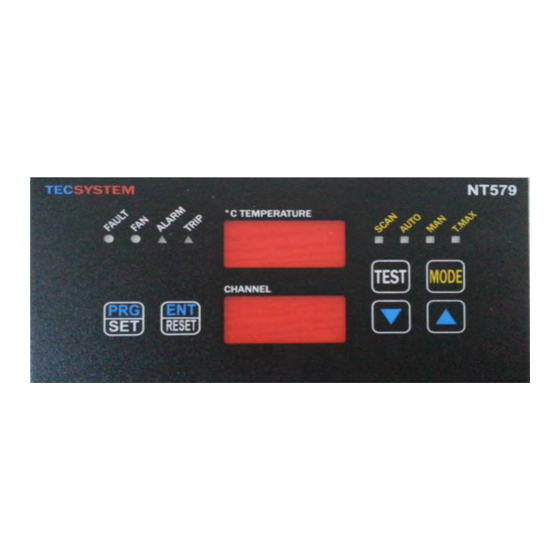
- Page 32 TECSYSTEM SHANGHAI 16)灯光测试 建议定期执行LED报警指示灯测试。 如果要进行测试,则应当短按TEST键;这时所有的显示灯将会被亮起2 如果其中一个LED灯不工作,需将仪表返回TECSYSTEM公司或当地代 理公司进行维修(LED灯用户无法进行现场维修更换,需要整机返回工 厂维修)。 取消报警触点的功能输出 17) 如果您取消报警触点的功能输出,请按下RESET键:触点将自行断开, 但LED告警灯仍将继续闪烁,只有当相应的温度回降到设定的报警温 度以下时,LED报警指示灯自动熄灭。 重要提示 18) 当用户对变压器进行耐压或绝缘测试时,必须断开温控器的各种连接, 面板信息 19) 图示1 温度及报警 报警信息 信息显示屏 显示模式 操作按键 显示屏 操作按键 NT579-NT579 RS485 智能温控器...
- Page 33 L1-L2-L3的挑闸TRIP门限值 可设定范围从1~200° C 按此上下选择按键用于调整 所需门槛值 PRG/SET 续按此功能键,显示FAN YES 或NO 字符 续按此功能键可选择YES或 如果选择NO,请转至第14步 NO状态 骤操作 PRG/SET 续按此功能键,显示出厂时 设定的启动风机门槛值 按此上下选择按键用于调整 启动温度必须大于下边设定的 风机启动所需温度值 风机关闭温度 PRG/SET 续按此功能按键,显示风机 关闭温度值 按此上下选择按键用于调整 停止温度必须小于上边设定的 风机停止所需温度门槛值 风机启动温度 PRG/SET 续按此功能按键,显示HFn 每“n”小时风机自检运行5分 字样,进入风机自检设定模 钟。 no表示禁止该自检功能 续按此功能按键,设置风机 自检运行的间隔时间(每 ***小时) NT579-NT579 RS485 智能温控器...
- Page 34 升率(° C/秒)来作判定) 从“no”至最高为30° C/秒 按此上下选择按键用于调整所需 门槛值(参考第22页说明) (no:禁止该功能) PRG/SET 续按此功能按键,显示ADR 温控器Modbus通讯地址, 16~21步只是针对带通讯功能 续按此功能按键,设定地址 从1到255 PRG/SET 续按此功能按键,显示BDR字符 通讯的波特率 设定波特率 从2.4到38.4 PRG/SET 按此键,显示PAR字符 Modbus 字符的奇偶校验 按此键设定 可选择No,even,odd PRG/SET 按此键,END字符显示 按此键,保存设置,退出编程 如此时出现Err字符,代表前面 的编程错误,重新返回第2步 操作 1)如果按ENT按键结束编程后,屏幕显示ALL Err字符,则表示编程 中跳闸报警温度低于高温报警的温度,请去相关步骤做修改。 内置MODBUS模块介绍 这种内置MODBUS扩充模块内置在NT579温控中,它可以通过 ModBus RTU协议向RS485网络传输数据。 NT579-NT579 RS485 智能温控器...
- Page 35 TECSYSTEM SHANGHAI 工作注意事项 为了使模块正常工作,必须通过编程设定地址,波特速率和奇偶性校 验。 请参阅第20项编程中的第16~21步骤。 温度控制装置之间的串行通信只有当NT579温控处于已知模式中 (Scan, Auto, Man eT.Max)的温度控制工作模式中才被激活。 当其他功能,如编程,编程显示和继电测试被激活时,则扩充模块 MODBUS网络数据传输 内置ModBus功能,使NT579温控器通过Modbus RTU协议连接到 RS485 Modbus通讯网路上,用户可以读取和写入第17-18-19-20项中 Modbus通讯报文表中的相关内容和数据。温控器始终处于从属通讯模 RS485 Modbus接线: 为了所使用的信号电缆能够确保网络的正常工作,我们建议按EIA RS485标准所建议使用的24AWG回线。 用于连接所有温控器于RS485通讯的线缆,在最后一个温控器的连 接末端,最好激活120欧姆终止端。 RS485通讯连接线,接线时须考虑极性并平放,以避免产生锐弯和 环状绕圈。 如有必要,也可以使用GND端子接地。 帧数据 异步传输帧由1个起始位、8个数据位和1个奇偶性校验位(偶数或奇 数,如奇偶性校验位已加载)和1个停止位构成。 适合的特速率:2400,4800,9600 , 19200和38400。 如没有特别规定,则字长(数据)为16比特。 NT579-NT579 RS485 智能温控器...
- Page 36 数据 -2 比特 循环冗余校验 从属请求: 从属地址 -1 比特 -1 比特 功能编码 -变量,取决于功能编码 数据 循环冗余校验 -2 比特 功能编码 ModBus 模块支持下列功能编码: 3(10): -保持寄存器读取 16(10): -复式寄存器写入 如果ModBus收到一个信息并且检测到一个循环冗余校验错误,则不 应答。 3(10)编码 请求: 从属地址、3(10)编码、HI启动地址、LO启动地址、HI点数和LO, Crc LO和Crc HI点数。 应答: 从属地址、3(10)编码、字节计数、HI数据、LO数据……., Crc LO 和Crc HI。 NT579-NT579 RS485 智能温控器...
- Page 37 TECSYSTEM SHANGHAI 错误码(异常码) 如果遇到错误请求,MODBus将做出答复并提供下列修改的编码和编 码错误: 1: - 无支持功能编码 2: - 错误数据地址 3: -错误数据(比如长度) 轮询频率 回答一个呼叫时限不得超过1秒;因此我们建议在较低的持续时间时 不要使用轮询频率。 CRC运算 对每个数据传输,本协议包括2个比特CRC-16。运算采用特征多项式 (11000000000000101B)并且其结果为处于信息包末端的«hung»。多项式 采用倒序方式并且压缩最重要的比特,因为其在运算中不是很有用。 参数描述 A-16比特寄存器 AL-在低侧 AH-在高侧 i,j,- KWH计算 (+) –异或 Di-信息包中的帧数据«i» N- 属于CRC的紫字符信息包中的 比特数,不包括2 G-多项式:1010-0000-0000-0001 Shr-右移位 NT579-NT579 RS485 智能温控器...
- Page 38 8) if NOT j=8 then go to 5 9) i+1->i 10) if NOT i=N then go to 3 11) A->in CRC (result is in the order L,H) 编码 ( ) 请求: 从属地址、16(10)编码、HI启动地址、LO启动地址、HI点数、LO 点数、字节计数、HI数据、LO数据……., Crc LO和Crc HI。 应答: 从属地址、16(10)编码、HI启动地址、LO启动地址、HI点数和LO, Crc LO和Crc HI点数。 报警门槛值(寄存器3-4-5-6)仅仅被写入通道1,并自动复制到第2和第3 NT579-NT579 RS485 智能温控器...
- Page 39 TECSYSTEM SHANGHAI 远程编程注意事项: 即使通过ModBus对温控器远程编程,您必须注意Alarm门限应低于 Trip门限,Fan-on门限必须低于Fan-off门限。 如果您错误地设置了这些门限,则NT579温控器,将不能继续数据编 程和储存;接下来读数时,读到的数据是原来编程所对应的数据。 当发送了一个写入请求后,监视器会用大约1秒钟的时间将它储存在 可擦除只读储器中,然后需要几秒钟重启;在储存阶段,ModBus将不再 处理其它的请求。 如果当前写入请求成功,温控器将自动复位并进入下一步新的编程 数据设定。 负的温度数值将会以2个字节加以显示负数。(FF代表负数) 各个通道的记录可通过编码3查看,从地址1到地址18(Modbus报 文表中) 工作注意事项: 选择Modbus inside 功能,NT579温控器可以通过MODBUS RTU协议 与RS485网络连接,通过读写注解,读取和写入报文表中相应的参数。 NT579-NT579 RS485 智能温控器...
- Page 40 TECSYSTEM SHANGHAI Modbus 报文表结构说明: Modbus 通讯规约记录表被分成2大部分: 从地址1到地址18,是所有通道的关于温度的内容信息 数据显示中2个高位字符 是用于正、负区分 管理的 地址的高字节:00 代表+,FF代表 - 地址的低字节代表温度数值 从地址41到53是所有关于报警、控制信息等方面的内容 在这些里面,寄存器中就不会出现正负的情况了, 寄存器地址高字节数值永远是0 地址的低字节是数据 如果目录中的操作形式不符合上述两部分内容的形式,控制系统中就 会出现异常乱码。 NT579-NT579 RS485 智能温控器...
- Page 41 Fan off set point 2’compl. Ch L2 from –20° 2’compl. sign temperature to 230 2’compl. Ch L2 from 1° to 2’compl. sign Maximum temperature 2’compl. Ch L2 from 1° to 2’compl. sign temperature alarm set point NT579-NT579 RS485 智能温控器...
- Page 42 2’compl. sign from 1° to 220 alarm set point 2’compl. Ch L3 temperature 2’compl. sign from 1° to 220 trip set point 2’compl. Ch L3 temperature 2’compl. sign from 1° to 220 Fan on set point NT579-NT579 RS485 智能温控器...
- Page 43 L2 Ch L2 story Alarm history See CHn story note channel L3 Ch L3 story Alarm history setting fan test 0=No test cycle (hours) 1÷ 200h detector tem- 0=No FCD perature incre- ment fast 1÷ 30° /sec NT579-NT579 RS485 智能温控器...
- Page 44 BIT 0 Not used TRIP ALARM Not used CH L1-L2-L3 STORY BIT 7 BIT 6 BIT 5 BIT 4 BIT 3 BIT 2 BIT 1 BIT 0 Not used TRIP ALARM Not used Not used Not used NT579-NT579 RS485 智能温控器...
- Page 45 接线端子排没有正确插进到位或接线端子上 的电源线没有拧紧或电源线烧断。 即使有电源供应与连接的情况下,仪表仍然 检查电源的接线正负极性是否正确(详见23 无法启动。 页) 措施:先取下检查,并重新安装。 检查Pt100传感器的连接。可能传感器接线 CH L1-L2-L3三通道处于FOC/FCC故障 不良或损坏。 措施:检查或更换已损坏的传感器。 由于强干扰导致内存数据损坏或缺陷。 请参阅本规范的第9条说明。如果此问题仍 当启动时,显示“ECH”错误信息 然存在,请与TECSYSTEM S.r.l.公司技术部 门取得联系。 所有的通道均处于FCC(短路)传感器报警 传感器接线端子排接线错误或端子内短路。 状态 或者传感器探头所处的温度低于-15° C. 所有的通道均处于FOC(开路)传感器报警 传感器接线连接不良,松动脱落。 或者是传感器检测到的温度超过了230° C. 状态 请与TECSYSTEM S.r.l.公司技术部门取得联 一个或多个通道错误温度显示 系。 此现象是由传感器损坏或者相应接线不良引 跳闸(TRIP)触点触发,但温度处于正常 起。通过T.MAX功能查看报警故障通道, 水平。 检查对应的接线端子或更换对应的传感器。 NT579-NT579 RS485 智能温控器...
- Page 46 TECSYSTEM SHANGHAI 21) 有关FCD功能的说明: FCD功能是NT系列温控器新增的一种针对PT100探测器的动态监控功能 如果温度探头被意外损坏,则突出的问题就是探头自身阻抗快速增加和 变化,因此导致温控器显示的监测温度迅速变化。 显然,这种温升并不是被监控保护的电力设备比如电动机,干式变压器 或封闭式变压器等自身故障引起的。 因此,这时候必须要监定为传感器处于故障状态以避免输出(ALARM) 高温报警信号甚至是跳闸(TRIP)等误报警事故。 当温控器是应用于对电机马达的监控时,快速温升FCD报警的定义不能 单指传感器故障,也可能是转子发生被卡住或者空转的故障状态,因此 用户应进行按不同的应用情况为FCD报警作不同的定义与应用。 当温升速率超过设定的速率(n° C/秒)(n值:从1到30),通过激活 FCD功能,温控器可以通过输出触点54-55输出FAULT错误报警信号。 通过参数设定,用户可以根据不同的使用要求选择如下不同的精度等 级: 从1至10:高灵敏度,用于即时探测电动机转子失速情况。 从10至20:平均灵敏度,用于监测影响传感器采集数据,线路连接不良 以及传感器缺陷等各种干扰信息。 从20至30:低灵敏度,用于的场合是,高灵敏度设置可能会导致不必要 的FCD功能中的错误报警 设置“no”模式,则FCD功能被禁止。 当一个通道出现FCD/FAULT故障报警时,相关的高温报警(ALARM) 和跳闸(TRIP)报警功能将被锁住,只是显示温度快速升高的FCD报 警,避免产生错误的高温报警(ALARM)和跳闸(TRIP)报警。 按下Reset键删除所有通道的FCD信号,检测修复仪表故障。 NT579-NT579 RS485 智能温控器...
- Page 47 22) 安装及线路联接: 嵌装开口尺寸:152*76mm;用附带的紧固件进行锁紧。 图示2 PT100传感器连接 白色线 红色线 红色线 CH L1 CH L3 CH L2 控制输出连接 特别说明:通电时故障报警继电器将断开;断电后或故障发生时故障报警继电器将闭合。 风机无源输出,节点容 量:12A@250Vac, (cos Φ=1) 54 55 50 51 56 57 52 53 风机控制 高温报警 故障报警 跳闸报警 电压:18~36 Vdc 必须注意正负极性 RS485通讯输出连接(标准型产品无) RS485输出连接 仪表后面板实物图 NT579-NT579 RS485 智能温控器...
- Page 48 TECSYSTEM SHANGHAI 23) 质保承诺: 本产品享受从购买之日起12个月的质保期。如在质保期内发生因产品 本身的生产工艺不符,校准不良等原因造成的质量问题或泰狮智能温控 (上海)有限公司的自身原因造成的产品不良,我们将免费维系或更 换。 如果是客户不按使用说明使用操作或其它客户原因造成的产品不良,不 属于免费保修范围,如需维修或更换,客户需承担相关费用。 注意: 为了保护环境,废旧产品,需要隔离送废品回收处,或返回我司进行专 业回收处理。 NT579-NT579 RS485 智能温控器...
Need help?
Do you have a question about the NT579 and is the answer not in the manual?
Questions and answers